External tire pressure gauge, mounting structure thereof and corresponding dismounting tool

A technology for installing structures and loading and unloading tools, which is applied in hand-held tools, manufacturing tools, tire measurement, etc. It can solve the problems of small screw size, inconvenient operation of screws, inconvenient screw alignment with screw holes, etc., and achieve the effect of fastening the connection relationship

Inactive Publication Date: 2014-03-12
STEELMATE CO LTD
View PDF1 Cites 1 Cited by
  • Summary
  • Abstract
  • Description
  • Claims
  • Application Information

AI Technical Summary

Problems solved by technology

Although this scheme does achieve the intended purpose, it has been found in practice that the size of the screws fastened on the valve is very small, and the space between the hub and the base is also very narrow, which makes it difficult to align the screws by hand. screw holes, and it is not convenient to use a screwdriver to align the nut of the screw, and it becomes very inconvenient to operate the screw
Moreover, it is generally necessary to set two or three screws in the radial direction of the valve to form a relatively stable and balanced mechanical structure. Users need to operate multiple screws to install or disassemble the tire pressure gauge, which is inconvenient.
[0005] On the other hand, the smaller the size of the tire pressure gauge, the less convenient it is to install and disassemble manually between its packaging kit and its base. Moreover, the aforementioned patent application does not provide a design that facilitates cooperation with the disassembly work. Therefore, lead to the imperfection of the technical solution

Method used


Image

  • External tire pressure gauge, mounting structure thereof and corresponding dismounting tool
  • External tire pressure gauge, mounting structure thereof and corresponding dismounting tool
  • External tire pressure gauge, mounting structure thereof and corresponding dismounting tool

Examples


Embodiment Construction

[0038] Below in conjunction with accompanying drawing and embodiment the present invention will be further described:

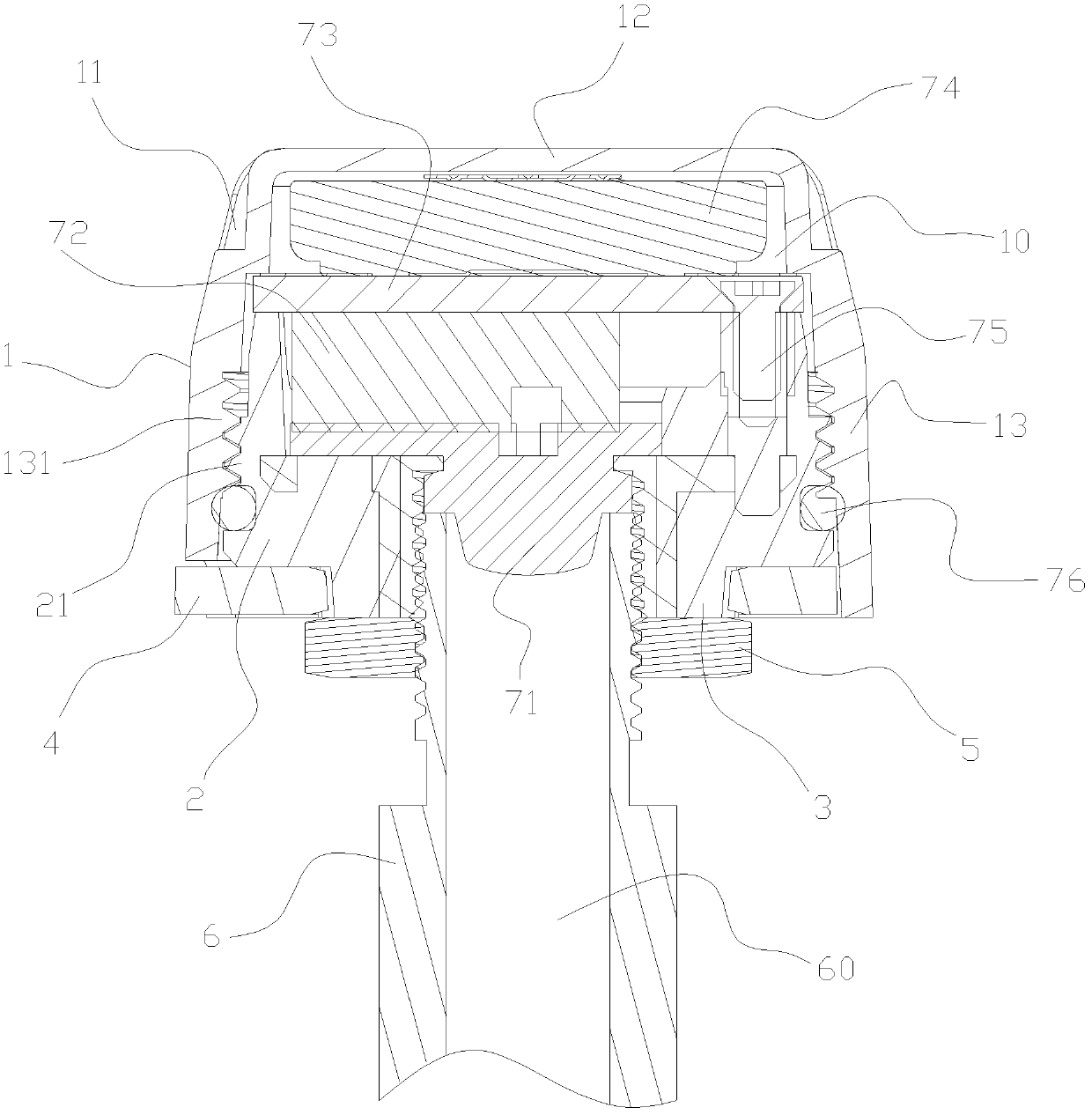
[0039] see figure 1, the external tire pressure gauge of the present invention is installed on the valve stem 6 of the tire of the vehicle, and the valve on the valve stem 6 is pushed open by a push rod 71, so that the pressure inside the tire is transmitted to the tire pressure gauge The internal pressure sensor 72 enables the sensor 72 to measure the current tire internal pressure, and transmits a signal representing the pressure into the air through a corresponding control circuit (not shown) and an antenna 75, so as to be detected by the monitoring unit (not shown) in the car. Figure) receiving processing, so as to complete the detection of car tire pressure.

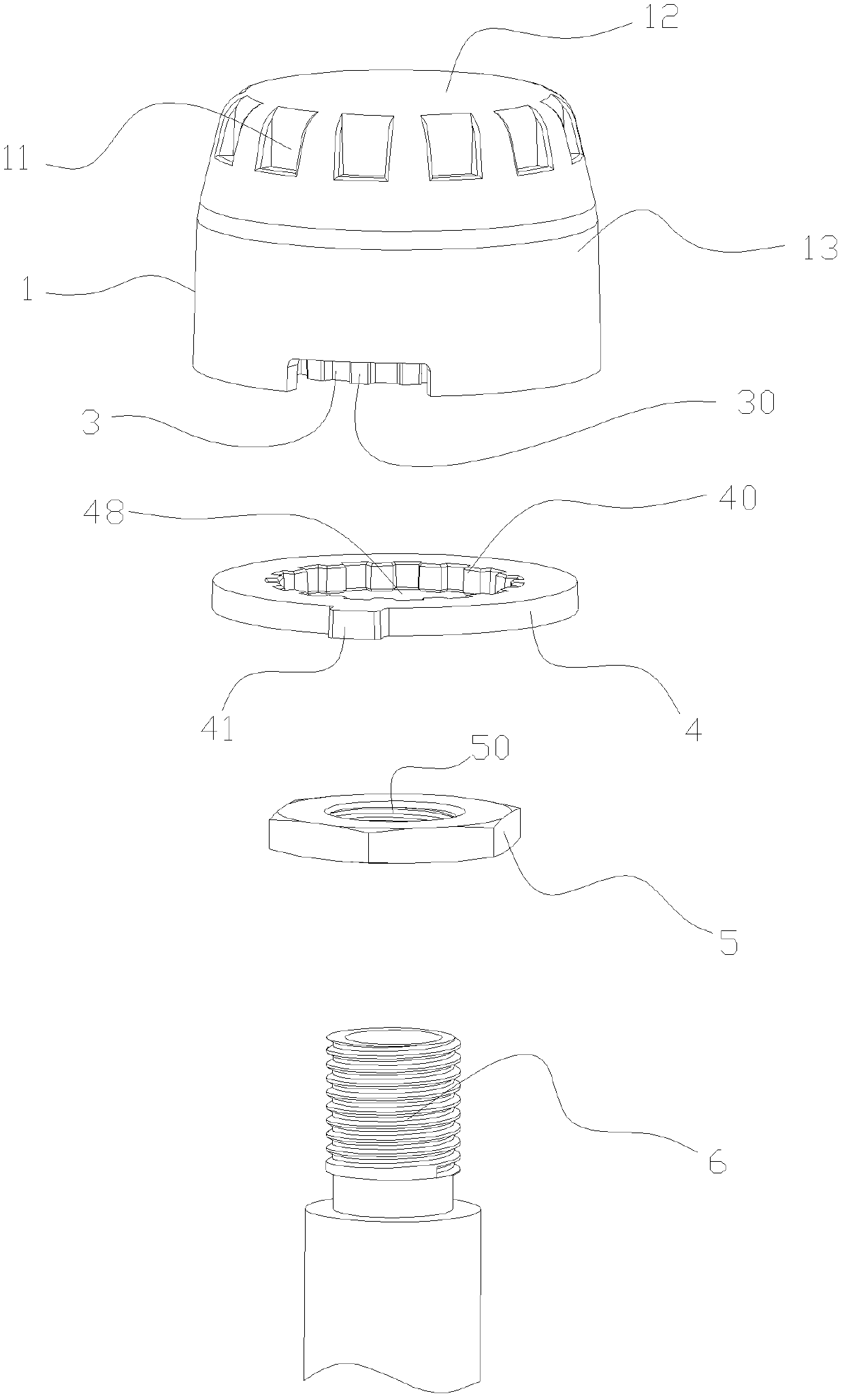
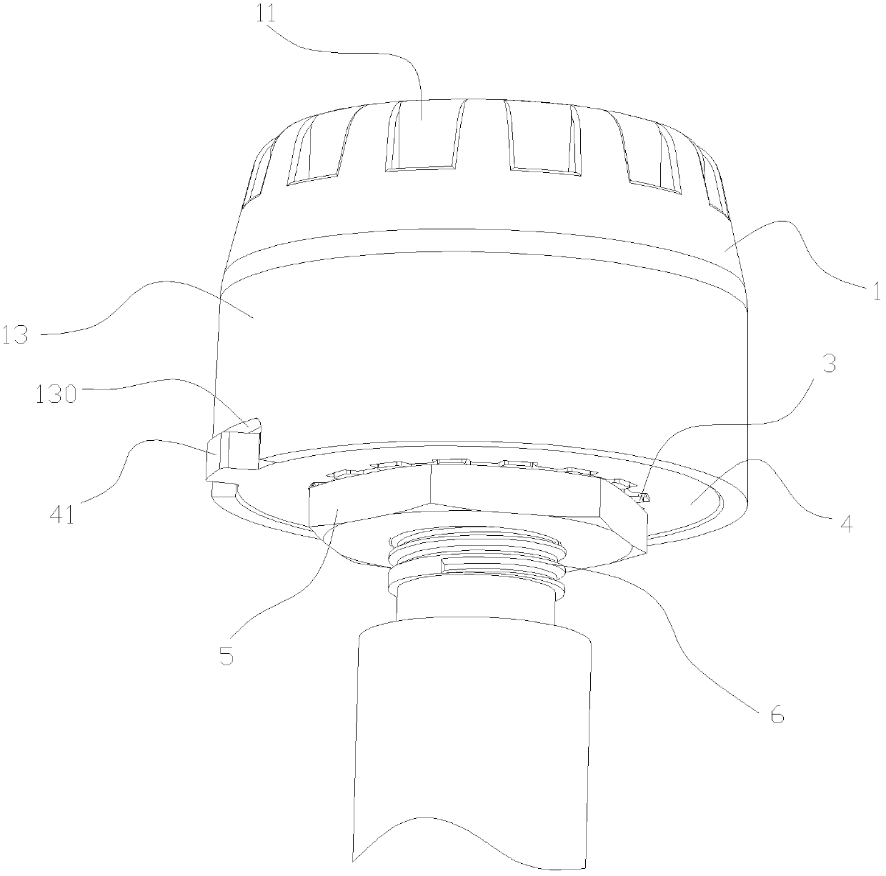
[0040] refer to figure 1 , the external tire pressure gauge of the present invention provides an installation structure with an internal installation space 10, a pressure sensor 72, a circuit boa...


PUM


Abstract

An external tire pressure gauge mounting structure includes a base and a cap; the base and cap are locked together to provide an internal mounting space; the mounting structure also includes a gear, a cushion ring and a locking member; the gear is fixed on the base and has teeth; a through hole is defined in the cushion ring and teeth is provided on a sidewall of the through hole; the gear is inserted into the cushion ring, and the teeth of the cushion ring and gear mesh each other; the locking member is pressed against the cushion ring and gear; the locking member, gear and base all have their threaded holes. Also disclosed is a handling tool used for above mounting structure. The invention makes improvements upon the mounting structure of the tire pressure gauge and provides a handling tool which is easy to use. As such, mounting and dismounting of the tire pressure gauge becomes convenient.

Description

technical field [0001] The field of automobile tire pressure detection equipment of the present invention specifically relates to an external tire pressure gauge installation structure, and naturally also relates to an external tire pressure gauge adopting this installation structure, and at the same time relates to an external tire pressure gauge corresponding to this installation structure Meter loading and unloading tools. Background technique [0002] The application of external tire pressure gauges is becoming more and more common, and its principle is well known. At present, the improvement made in the industry for external tire pressure gauges mainly focuses on its product structure. On the one hand, it pursues the minimization of product size, on the other hand, it pursues The stability and safety and anti-theft of the installation structure. [0003] Please refer to the CN102310734A patent application published by the Chinese Patent Office on January 11, 2012, whic...

Claims


Application Information

Patent Timeline
Patent Type & Authority Patents(China)
IPC IPC(8): B60C23/04B25B27/14
CPCB60C23/0496B25B27/14Y10T29/53909B60C23/04
Inventor 李植滔
Owner STEELMATE CO LTD
Why Eureka
Try Eureka