
Display device for acceleration/deceleration state of automobile

A state display, acceleration and deceleration technology, applied in signal devices, vehicle parts, transportation and packaging, etc., can solve the problems of not reflecting the changes in the running speed of the car, difficult to find it in time, and unable to reflect the car, etc., to achieve intuitive The effect of observation and judgment, improving operation efficiency and practical information

Inactive Publication Date: 2012-08-15
周亦武
View PDF4 Cites 2 Cited by
  • Summary
  • Abstract
  • Description
  • Claims
  • Application Information

AI Technical Summary

Problems solved by technology

[0002] At present, there is no device on the car to indicate the change of running speed to the rear. The driver of the rear car can only judge the state of the running speed change of the front car based on experience. Even if the change of the speed of the front car can be judged based on experience, it often takes a long time. , it is difficult to achieve instant detection
What the car brake light can display is the brake operation action of the car driver, but it cannot reflect the specific information of the change in the running speed of the car itself, let alone the change in the running speed of the car caused by the change of fuel supply.
At present, the various rear display lights of the car cannot provide the actual change information of its moving speed to the rear, which is very unfavorable for the rear car to grasp the speed change of the front car in time and take corresponding operations to avoid misjudgment and accidents

Method used


Image

  • Display device for acceleration/deceleration state of automobile
  • Display device for acceleration/deceleration state of automobile
  • Display device for acceleration/deceleration state of automobile

Examples


Embodiment Construction

[0011] The present invention will be further described below in conjunction with the drawings and embodiments:

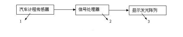
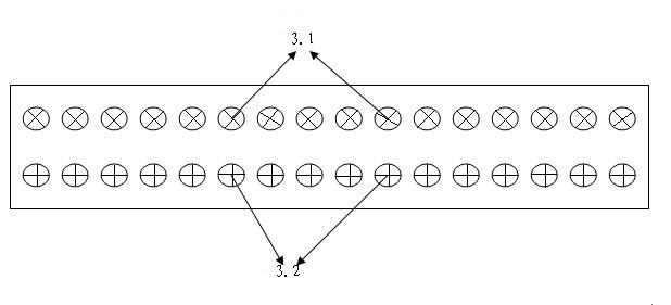
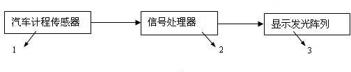
[0012] Labels in the figure: car meter sensor 1; signal processor 2; display array illuminator 3; deceleration display array indicator 3.1; acceleration display array indicator 3.2.

[0013] The working principle of the present invention is: install a pulse log sensor to measure the mileage of the car in the car, calculate the instant speed of the car by measuring the pulse of the log sensor, and set the instant speed of the first measurement as v 1 , The instant velocity of the second measurement is v 2 , The time between two measurements is denoted by T, the acceleration and deceleration state of the car, that is, the acceleration (deceleration) speed a can be expressed as:

[0014] a=(v 2 -v 1 ) / T

[0015] The technical scheme adopted by the present invention is to display the measured and calculated acceleration and deceleration change values ​​through the display array ...


PUM


Abstract

The invention relates to a display device for an acceleration / deceleration state of an automobile. The display device is characterized by consisting of an automobile odometer sensor, a signal processor and a display array light emitter. The display array light emitter of the display device is mounted at the rear part of the automobile to provide indication information on the actual change of a moving speed of the automobile for a rear automobile, so that the display device has the characteristics of instant display, practical information and clear display mode. The rear automobile can instantly accelerate an accelerator so as to correspondingly advance in an accelerating manner and keep an original distance between the two automobiles when the front automobile is accelerated through observing the acceleration / deceleration state displayed by the display array light emitter of the front automobile, and thus the running efficiency is increased; and the accelerator of the rear automobile is instantly decelerated to correspondingly advance in a decelerating manner when the front automobile is decelerated, so that the occurrence of rear-end collision accidents is prevented.

Description

Technical field [0001] The invention relates to a display device for the acceleration and deceleration state of an automobile. It is an indicator light installed on the rear of the automobile to display information about changes in the running speed of the vehicle, that is, the vehicle is in an acceleration and deceleration state during operation. Background technique [0002] At present, there is no device on the car to indicate the speed change to the rear. The driver of the rear car can only judge the state of the speed change of the front car based on experience. Even if the change in the speed of the car in front can be judged based on experience, it often takes a long time. , It is difficult to find out instantly. Automobile brake lights can display the brake operation actions of the car driver, but cannot reflect the specific information of the change in the running speed of the car itself, let alone the change in the running speed of the car caused by the change in fuel s...

Claims


Application Information

Patent Timeline
Patent Type & Authority Applications(China)
IPC IPC(8): B60Q1/54
Inventor 周亦武
Owner 周亦武
Learn More