Electroosmosis belt type squeezing sludge dehydration equipment

A technology of sludge dehydration and electroosmosis, applied in the direction of dehydration/drying/concentrated sludge treatment, etc., can solve the problems of poor sludge dehydration effect, achieve the effect of improving the dehydration efficiency of pressing, convenient maintenance, and easy replacement

Active Publication Date: 2012-09-05
江苏百新环境工程有限公司
View PDF7 Cites 17 Cited by
  • Summary
  • Abstract
  • Description
  • Claims
  • Application Information

AI Technical Summary

Problems solved by technology

Generally speaking, the sludge dewatering effect of the existing belt press sludge dewatering device is not good, and there is a big gap between the actual demand and the actual demand.

Method used


Image

  • Electroosmosis belt type squeezing sludge dehydration equipment
  • Electroosmosis belt type squeezing sludge dehydration equipment
  • Electroosmosis belt type squeezing sludge dehydration equipment

Examples


Embodiment 1

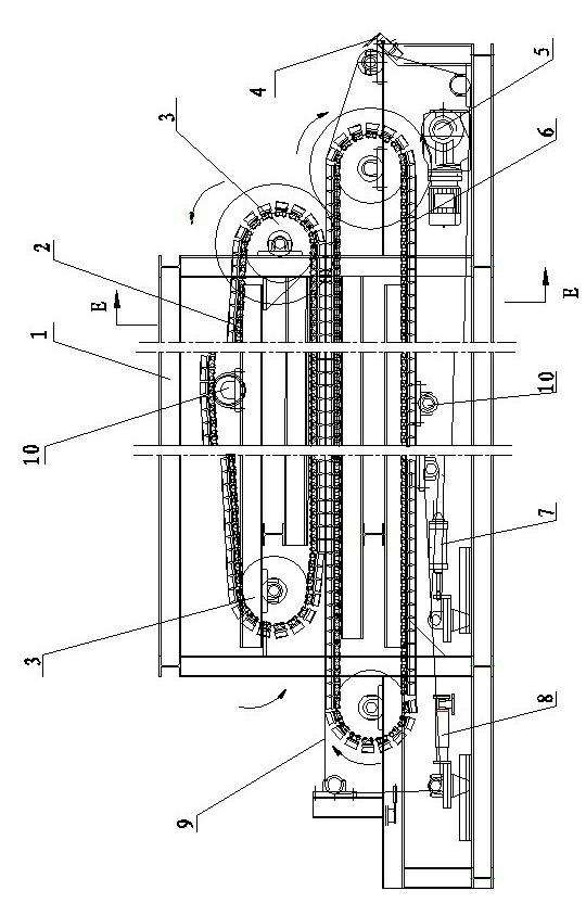
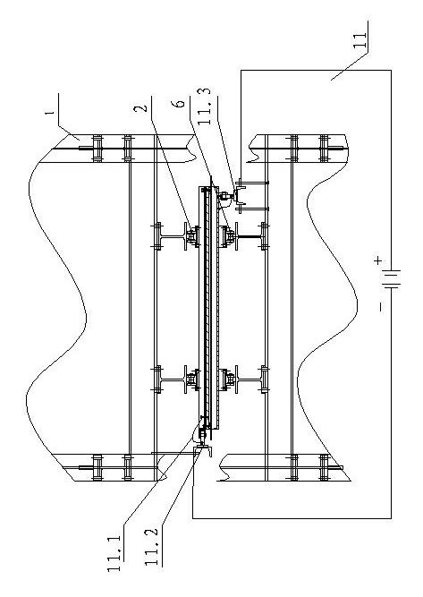
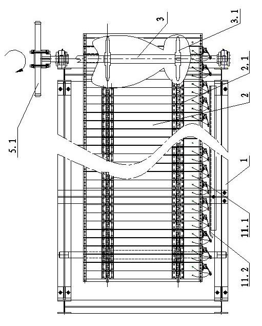
[0027] figure 1 and figure 2 The shown embodiment is an electroosmotic belt press sludge dewatering equipment with a daily output of 10 tons of sludge cake with a dryness of 50%, which includes a frame 1, an upper press belt 2, a transmission shaft 3, a scraper 4, a power machine 5, Lower press belt 6, tensioning device 7, deviation correcting device 8, filter belt 9, support roller 10 and power supply 11. Frame 1 is basic structure among the present invention, and it is the horizontal position elongated steel structure truss that it welds with I-beam, is provided with the wedge-shaped flat groove that width is 1600mm along the length direction at the waist. The wedge-shaped flat groove is a tapered structure, and the height of the inlet end is 12mm larger than the height of the outlet end. When the wedge-shaped flat groove of this size passes through the upper press belt 2, the lower press belt 6 and the filter belt 9, the wet sludge of 30mm is flatly spread, and the press...

Embodiment 2

[0029]This embodiment is an electroosmotic belt press sludge dewatering equipment with a daily output of 40 tons of sludge cake with a dryness of 50%. Its main structural parameters are: the width of the wedge-shaped flat groove of frame 1 is 2800mm, and the height of the inlet end is 18mm larger than that of the outlet end. The width of the upper press belt 2 and the lower press belt 6 is 2300mm. Because the width is larger, in order to increase the strength, the upper press belt 2 and the lower press belt 6 are all manufactured with 5 chains in the present embodiment. The width of the filter belt is 2500mm, and the voltage of the power supply 11 used is 100V. In a wedge-shaped flat groove of this size, the upper press belt 2 and the lower press belt 6 can produce a pressing force of 1.7kgf / cm on the wet sludge spread on the filter belt 9 for 30 mm 2 ~1.9kgf / cm 2 . The wet sludge squeezed in this example is urban domestic sewage sediment, and the degree of acid reduction i...


PUM

PropertyMeasurementUnit
widthaaaaaaaaaa
widthaaaaaaaaaa
widthaaaaaaaaaa

Abstract

The invention discloses electroosmosis belt type squeezing sludge dehydration equipment, which comprises a stander, an upper squeezing belt, transmission shafts, a scraper blade, power machinery, a lower squeezing belt, a tension device, a rectification device, a filter belt, supporting wheels and a power supply, wherein the upper squeezing belt and the lower squeezing belt which are supported and driven by the transmission shafts have the same structure, namely a track type structure which consists of two chains arranged at an interval and an upper bridge plate and/or a lower bridge plate which are/is transversely arranged according to pitches of the chains; the upper squeezing belt and the lower squeezing belt are respectively connected with the positive electrode and the negative electrode of the direct current power supply and clamp the filter belt to enter a wedged flat groove of the stander, namely a squeezing region under an electrophoresis condition, so that water molecules in sludge flow towards the lower bridge plates with negative levels; and therefore, the squeezing dehydration efficiency is greatly improved, the sludge is reduced obviously, and the produced high-dryness sludge cake is favorable for later-stage recycling application.

Description

technical field [0001] The invention relates to a kind of mechanical equipment for sludge dewatering. Specifically, the invention relates to a belt press sludge dewatering equipment under the condition of electroosmosis, which belongs to the technical field of environmental protection equipment. Background technique [0002] The by-product of treating industrial sewage and urban domestic sewage is viscous sludge, because this kind of sludge has high water content, is not easy to accumulate, is difficult to store and transport in a centralized manner, and is not convenient for later resource utilization. In order to meet the government's requirements on sludge reduction, recycling, and harmless treatment, physical dehydration is usually used in projects to obtain sludge cakes with a certain dryness. At present, the most widely used dewatering equipment in engineering is the belt press dehydrator. This type of equipment relies on the double-layer press belts that move synchron...

Claims


Application Information

Patent Timeline
Patent Type & Authority Applications(China)
IPC IPC(8): C02F11/12
Inventor 张宪如
Owner 江苏百新环境工程有限公司
Why Eureka
Try Eureka