Novel flywheel electromagnetic clutch brake structure

An electromagnetic clutch and brake technology, applied in the direction of electric components, electrical components, electromechanical devices, etc., can solve the problems of poor matching ability, low degree of standardization, poor interchangeability, etc., achieve strong matching ability, high degree of standardization, overcome matching The effect of poor ability

Inactive Publication Date: 2012-09-12
黄刚
View PDF0 Cites 1 Cited by
  • Summary
  • Abstract
  • Description
  • Claims
  • Application Information

AI Technical Summary

Problems solved by technology

[0005] Beneficial effects: Since the present invention adopts the structural method of installing the electromagnetic clutch brake inside the flywheel housing, power input or cut-off can be realized, and the flywheel can temporarily store the energy of the flange motor. Therefore, the flywheel electromagnetic clutch brake of this structure has switching The advantages of strong function, matching ability, high degree of standardization, and good interchangeability have achieved the purpose of the present invention, and effectively overcome the defects of poor matching ability, low degree of standardization, and poor interchangeability existing in the existing flywheel electromagnetic clutch

Method used


Image

  • Novel flywheel electromagnetic clutch brake structure
  • Novel flywheel electromagnetic clutch brake structure

Examples


Embodiment Construction

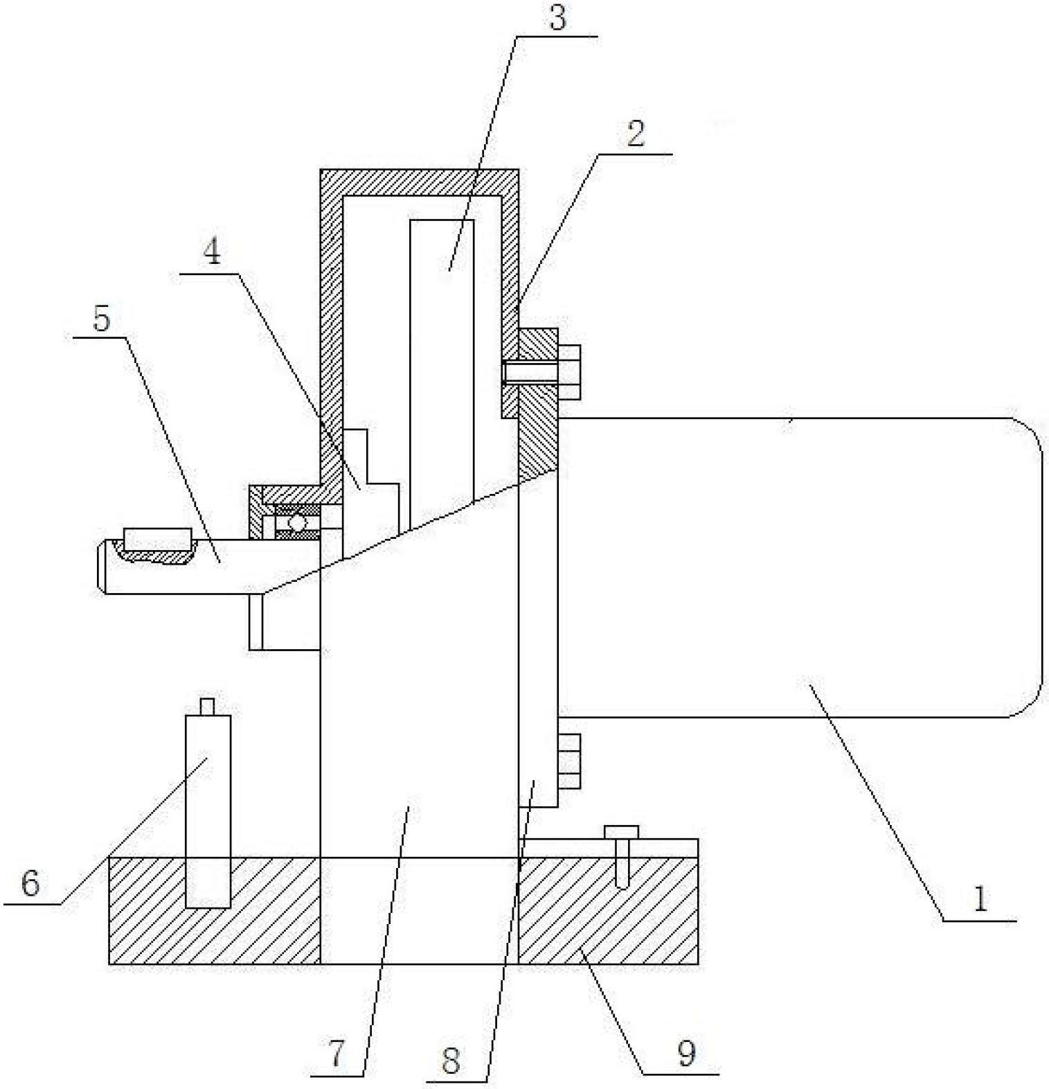
[0009] The flywheel electromagnetic clutch brake structure has a structure (9), the lower part of the structure (9) is connected with the transmission magnetic wheel pin (6) and the flywheel connecting sleeve (7), and a flange motor ( 1), the flange motor (1) is fixed by the fixing pin (8); the flywheel cover (2) is installed on the flange end of the flange motor (1), and the flywheel (3) is installed on the flywheel cover (2) On the output shaft of the flange motor (1), the electromagnetic clutch brake (4) and the output shaft of the flange motor (1) are coaxially installed in the inner cavity of the flywheel housing (2) at the left end of the flywheel (3), and the output The shaft (5) is coaxially installed on the flywheel cover (2) at the left end of the flywheel through the bearing and the output shaft of the flange motor (1), and one end of the output shaft of the flange motor (1) is connected to the electromagnetic clutch brake (4) Link to each other, and one end links t...


PUM


Abstract

Disclosed is a novel flywheel electromagnetic clutch brake structure. The lower portion of a structure body is connected with a transmission magnetic wheel pin and a flywheel connecting sleeve, a flange motor is mounted above the structure body and fixed by a fixing pin, a flywheel shell is mounted at a flange end of the flange motor, a flywheel is mounted above an output shaft of the flange motor of the flywheel shell, an electromagnetic clutch brake and the output shaft of the flange motor are mounted in an inner cavity of the flywheel shell at the left end of the flywheel coaxially, an output shaft and the output shaft of the flange motor are mounted above the flywheel shell at the left end of the flywheel coaxially through a bearing, one end of the output shaft of the flange motor is connected with the electromagnetic clutch brake, and the other end of the output shaft of the flange motor is connected with the output shaft.

Description

technical field [0001] The invention relates to a flywheel electromagnetic clutch and brake structure, in particular to a novel flywheel electromagnetic clutch and brake structure, which belongs to the technical field of electromechanical equipment. Background technique [0002] The flywheel electromagnetic clutch and brake structure is an important component of driving mechanical equipment. In actual work, it is often necessary to determine the power input or power cut-off according to the specific conditions of the work. In the actual application process, because there is no setting in the transmission system A special switching device, therefore, has the defects of poor matching ability, low degree of standardization, and poor interchangeability. Contents of the invention [0003] The purpose of the present invention is to provide a new type of flywheel electromagnetic clutch brake structure with switching function, strong matching ability, high degree of standardizatio...

Claims


Application Information

Patent Timeline
Patent Type & Authority Applications(China)
IPC IPC(8): H02K7/02H02K7/102
CPCY02E60/16
Inventor 黄刚
Owner 黄刚
Why Eureka
Try Eureka