Circuits at sending end, circuits at receiving end, interface switching module, and interface switching method

A technology of interface switching and sending end, which is applied in the field of receiving end circuit, transceiver circuit, interface switching module, and sending end circuit, and can solve the problems of complex hardware design and high cost

Inactive Publication Date: 2008-10-22
SUNPLUS TECH CO LTD
View PDF2 Cites 0 Cited by
  • Summary
  • Abstract
  • Description
  • Claims
  • Application Information

AI Technical Summary

Problems solved by technology

At present, the bridging unit of high-speed serial signals of SATA and SAS must use the structure of three or more physical layer transceivers (transceivers) to realize the mechanism of switching between multiple high-speed serial signals. The hardware design is relatively complicated and the cost is also low. higher

Method used


Image

  • Circuits at sending end, circuits at receiving end, interface switching module, and interface switching method
  • Circuits at sending end, circuits at receiving end, interface switching module, and interface switching method
  • Circuits at sending end, circuits at receiving end, interface switching module, and interface switching method

Examples


Embodiment Construction

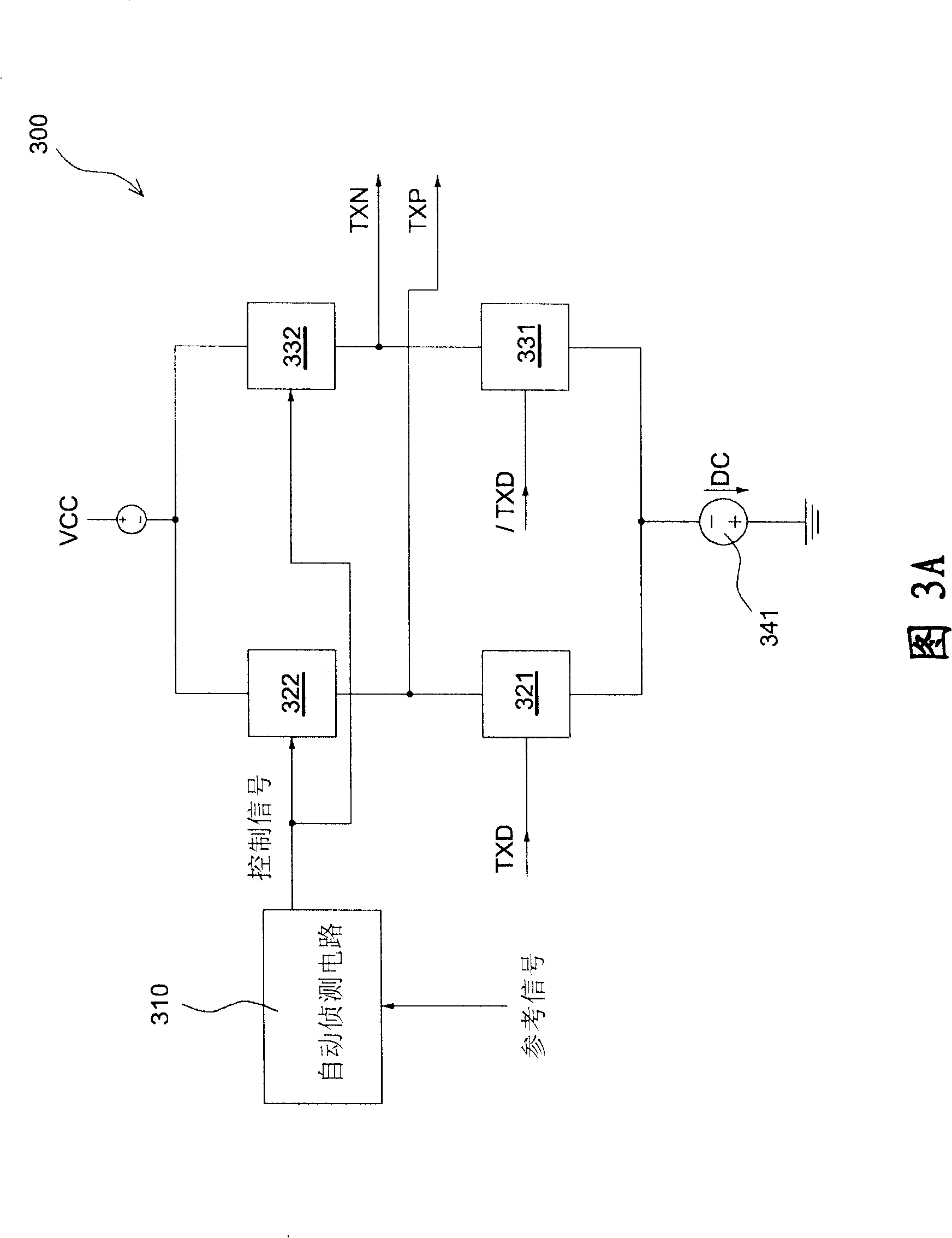
[0024] FIG. 3A is a circuit diagram of the sending end circuit of the present invention. Referring to FIG. 3A , the transmitting end circuit 300 of the present invention is applied to a SATA or SAS interface, and includes two resistor units 322 , 332 , two switch units 321 , 331 , an automatic detection circuit 310 and a current source 341 .

[0025] The automatic detection circuit 310 enables or disables a control signal according to the potential level of an external reference signal, so as to control or adjust the equivalent impedance value of the resistor units 322, 332, thereby controlling whether to transmit data signals. The resistance units 322, 332 are controlled by the control signal. When the control signal is enabled, the equivalent impedance value of the resistance unit 322, 332 is adjusted to a preset impedance value (for example, 50 ohms); When disabled, the equivalent impedance of the resistor units 322 and 332 is adjusted to a high impedance (Hi-Z). The input...


PUM


Abstract

An interface used on SATA or on SAS is prepared as utilizing transistor as impedance regulation component and utilizing impedance regulation mode to coordinate with external circuit and external layout design to let two SATA or two SAS connection interfaces be able to carry out switching-over automatically for making single system be able to have two SATA or two SAS connection interfaces simultaneously.

Description

technical field [0001] The present invention relates to a computer transmission interface, in particular to a serial advanced technology adapter interface (serial advanced technology attachment, hereinafter referred to as SATA) or a serial attached small computer system interface (serial attached small computer system interface, hereinafter referred to as SAS), the sending end circuit, the receiving end circuit, the transceiver circuit, and the interface switching module and method. Background technique [0002] Figure 1 is a circuit diagram of the sending end in the SATA and SAS specifications. FIG. 2 is a circuit diagram of a receiver in the SATA and SAS specifications. [0003] Referring to FIG. 1 and FIG. 2 , the transmitting end circuit 100 includes a switch 110 and two variable resistors 101 for receiving a transmitting data signal TXD to generate a first transmission signal TXP and a second transmission signal TXN. The receiver circuit 200 includes a differential am...

Claims


Application Information

Patent Timeline
Patent Type & Authority Patents(China)
IPC IPC(8): G06F13/38
Inventor 吴育星周明忠林虹芝
Owner SUNPLUS TECH CO LTD
Why Eureka
Try Eureka