Supercharge Your Innovation With Domain-Expert AI Agents!

Directly applicable electrical bushing

An electrical bushing and bushing technology, applied in electrotherapy, welding/welding connection, treatment, etc., can solve problems such as laborious and difficult automation

Active Publication Date: 2012-09-19
HERAEUS PRECIOUS METALS GMBH & CO KG
View PDF42 Cites 9 Cited by
  • Summary
  • Abstract
  • Description
  • Claims
  • Application Information

AI Technical Summary

Problems solved by technology

Also, the process of utilizing solder rings to connect leads to previously metallized insulators is a laborious and difficult to automate process

Method used


Image

  • Directly applicable electrical bushing
  • Directly applicable electrical bushing
  • Directly applicable electrical bushing

Examples


Embodiment Construction

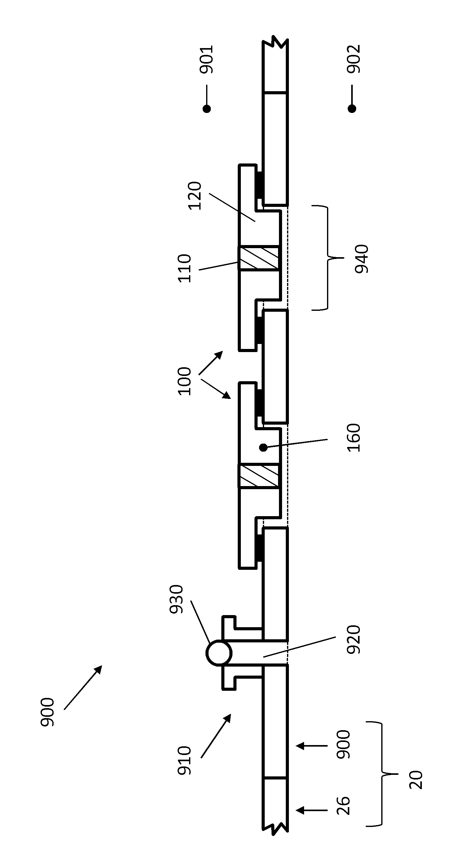
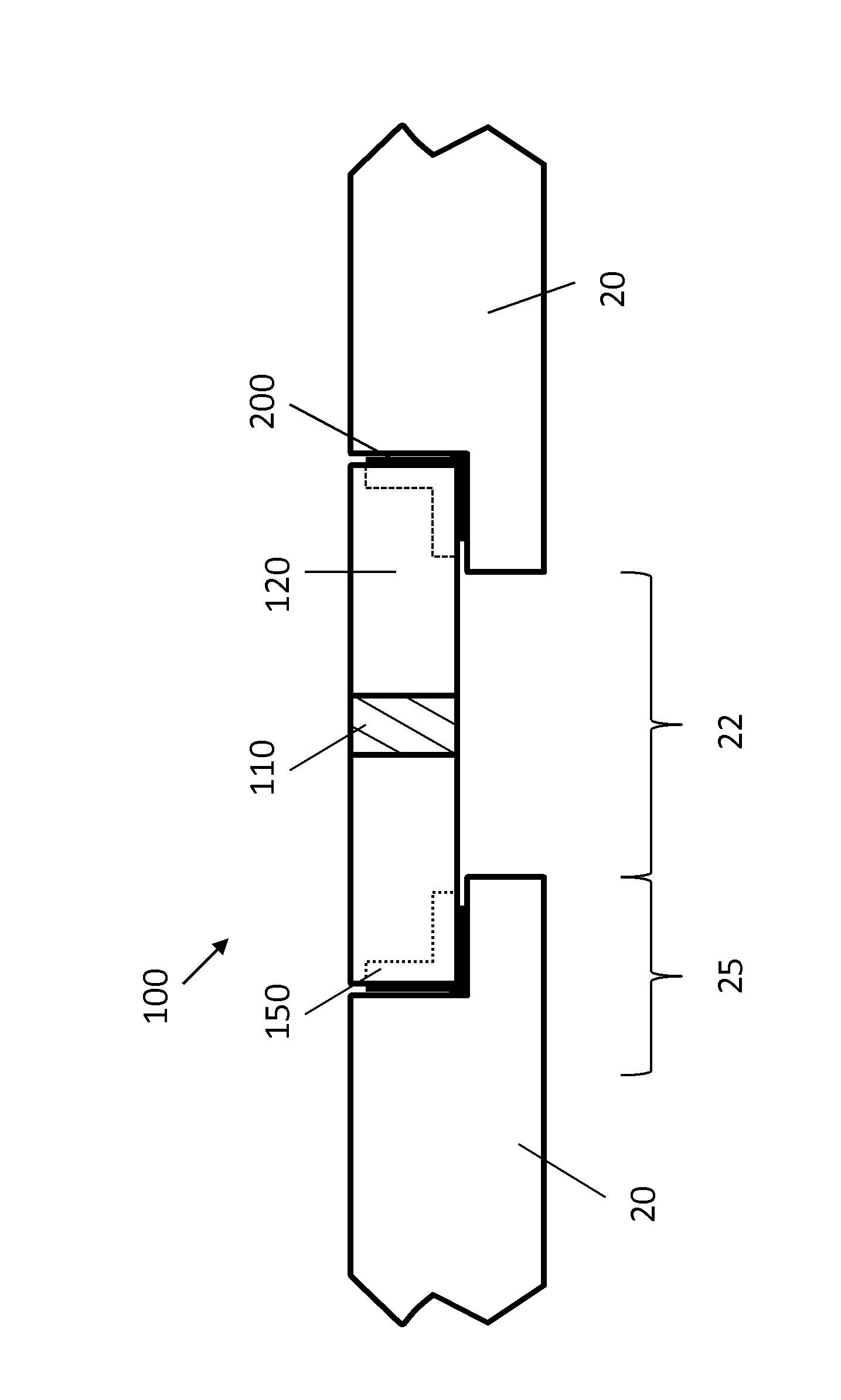
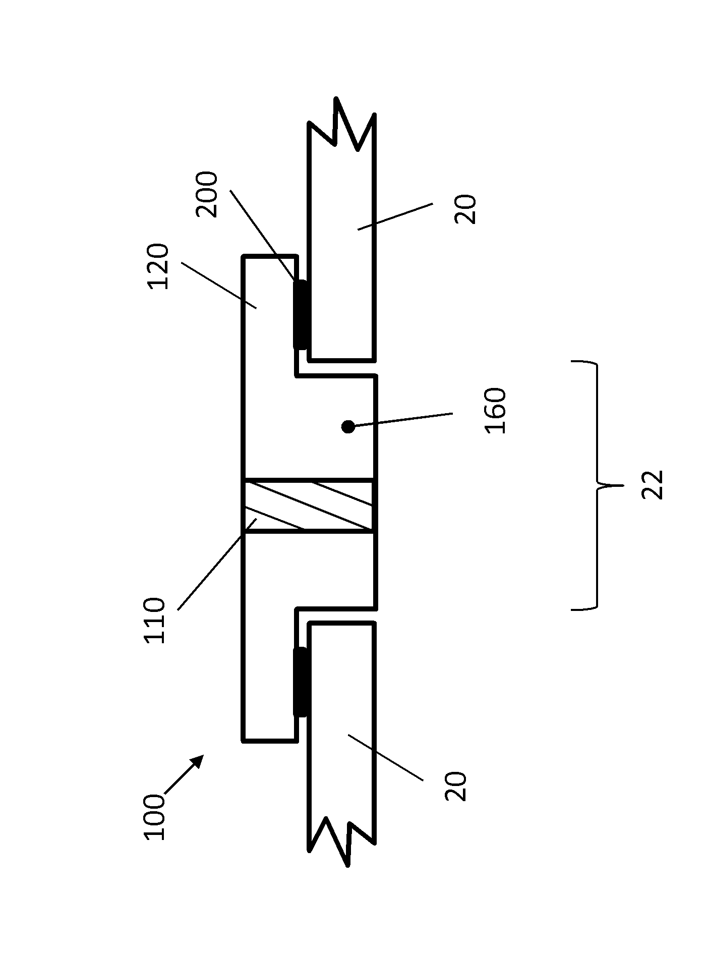
[0100] figure 1An active implantable medical device 10 is shown. The electrical bushing 100 is part of the device 10 . Device 10 includes housing 20 . The circuit board 30 is provided inside the housing 20 and has the electronic unit 50 mounted thereon. The battery 40 supplies the required electrical power to the electronic unit 50 . Capacitor 45 may be used to store the pulse energy required by the implantable defibrillator. The electrical bushing 100 according to the invention is inserted into the housing 20 in such a way that the electronic unit 50 is hermetically sealed from the surrounding environment. The electrical bushing 100 according to the present invention allows to achieve less than 1 x 10 -9 Helium leak rate atm*cm3 / sec. Moreover, it is resistant to cleaning and sterilization methods.

[0101] The channels of the electronic unit 50 are connected to the conductive elements 110 of the electrical bushing 100 by means of internal connecting elements 55 . Sai...


PUM


Abstract

One aspect relates to an electrical bushing(100) for use in a housing(20) of an active implantable medical device(10), whereby the electrical bushing(100) includes at least one electrically insulating base body(120) and at least one electrical conducting element(110), whereby the conducting element(110) establishes, through the base body(120), at least one electrically conductive connection between an internal space(23) of the housing and an external space(24), whereby the conducting element(110) is hermetically sealed with respect to the base body(120), and whereby the at least one conducting element(110) includes at least one cermet. One aspect provides the base body(120) to include a contact region(150), whereby the base body(120) can be connected to the housing(150) in a firmly bonded manner by means of the contact region(150).

Description

technical field [0001] The present invention relates to an electrical bushing for use in the housing of an active implantable medical device. Background technique [0002] An electrical bushing for an implantable medical device having the features of the preamble of claim 1 is disclosed in the later published document DE102009035972. Furthermore, the use of at least one conductive element comprising a cermet in an electrical bushing for an implantable medical device and a method of making an electrical bushing for an implantable medical device are disclosed. [0003] Numerous electrical bushings are known from the prior art for a variety of different applications. 作为实例包括US4678868、US7564674 B2、US2008 / 0119906A1、US7145076B2、US7561917、US2007 / 0183118A1、US7260434B1、US7761165、US7742817B2、US7736191B1、US2006 / 0259093A1、US7274963B2、US2004116976A1、US7794256、US2010 / 0023086A1、US7502217B2、US7706124B2、US6999818B2、EP1754511A2、 US7035076、EP1685874A1、WO03 / 073450A1、US7136273、US7765005、WO2008 / 1...

Claims


Application Information

Patent Timeline
Patent Type & Authority Applications(China)
IPC IPC(8): A61N1/375H01R4/02
CPCA61N1/3754H04R2225/67
Inventor J.特勒切尔M.克姆普夫
Owner HERAEUS PRECIOUS METALS GMBH & CO KG
Features
  • R&D
  • Intellectual Property
  • Life Sciences
  • Materials
  • Tech Scout
  • Unparalleled Data Quality
  • Higher Quality Content
  • 60% Fewer Hallucinations
Learn More