Hot nozzle installation structure of hot runner system

A technology of installation structure and hot runner, applied in the field of molds, can solve the problems of copper erosion effect, limitation, glue leakage, etc., and achieve the effects of easy disassembly, avoidance of glue leakage, and convenient installation.

Inactive Publication Date: 2015-04-29
SHENZHEN SKYWORTH PRECISION TECH
View PDF4 Cites 2 Cited by
  • Summary
  • Abstract
  • Description
  • Claims
  • Application Information

AI Technical Summary

Problems solved by technology

Although the above-mentioned sealing structure is designed, since the contact surface between the hot runner manifold 300' and the hot nozzle 100' is a smooth surface, the gap-free contact between the two cannot be guaranteed under the clamping force, so There is still a risk of glue leakage
Moreover, this copper sealing ring 200' can only be used once, and must be replaced after the mold is cooled, and because copper has an erosion effect, this copper sealing ring cannot be used in some plastic processing. Therefore, this installation structure Not only limited but also has the problem of glue leakage

Method used


Image

  • Hot nozzle installation structure of hot runner system
  • Hot nozzle installation structure of hot runner system
  • Hot nozzle installation structure of hot runner system

Examples


Embodiment Construction

[0019] In order to make the object, technical solution and advantages of the present invention clearer, the present invention will be further described in detail below in conjunction with the accompanying drawings and embodiments. It should be understood that the specific embodiments described here are only used to explain the present invention, not to limit the present invention.

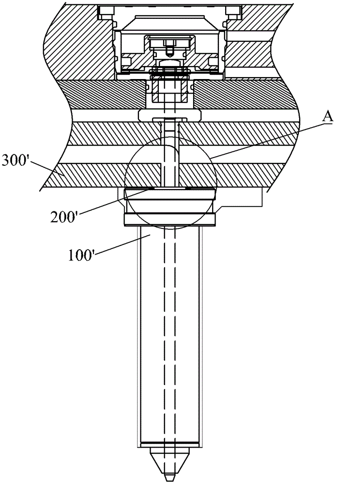
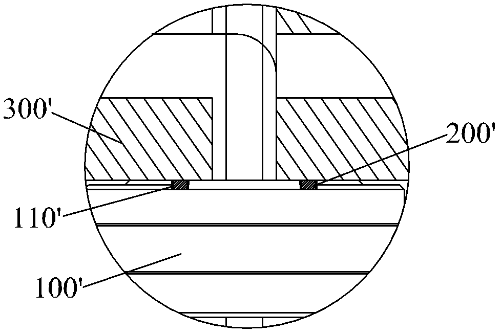
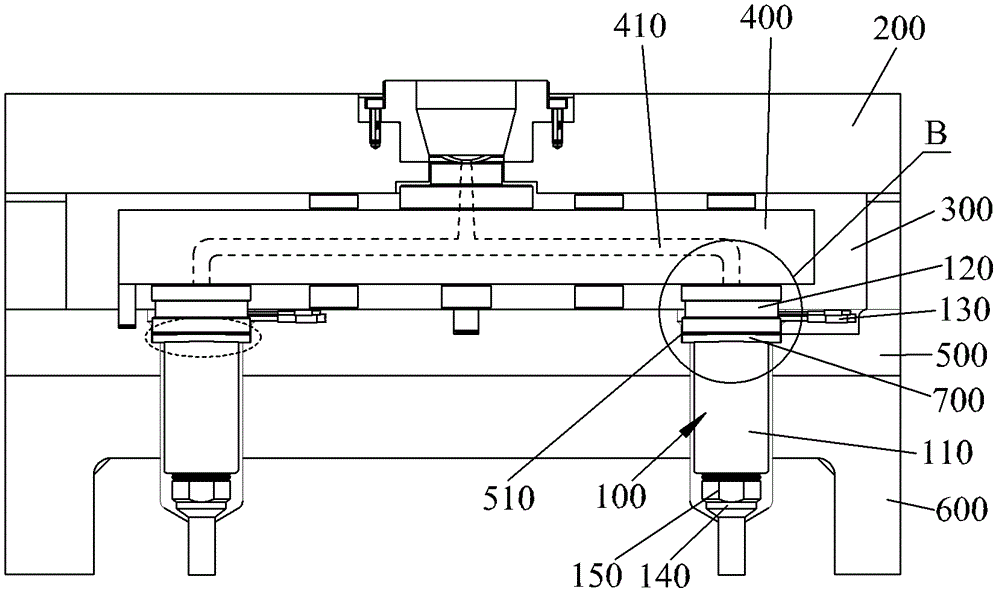
[0020] refer to image 3 , shows the installation structure of the hot nozzle 100 in the hot runner system provided by the present invention. The hot runner system includes a stacked upper template 200 , a hot runner plate 300 , a manifold 400 disposed in the hot runner plate 300 , a backing plate 500 placed below the manifold 400 , and a front template 600 . The hot nozzle 100 includes a body 110 , a positioning sleeve 120 sleeved on the top of the body 110 , and a heating ring 130 connected to the outer surface of the positioning sleeve 120 . The backing plate 500 is provided with a step groove...


PUM


Abstract

The invention relates to the technical field of moulds and provides a hot nozzle installation structure of a hot runner system. The hot nozzle installation structure comprises a spreader plate, a cushion plate, a front mould plate and a ladder groove which are sequentially located under the spreader plate. The ladder groove is arranged on the cushion plate and penetrates through the front mould plate. A hot nozzle comprises a body and a location sleeve sleeved at the top end of the body. The body stretches into the front mould plate from the ladder groove, the location sleeve is arranged on the step face of the ladder groove, and the top face of the location sleeve is contacted with the bottom face of the spreader plate. The hot nozzle installation structure further comprises a locking piece arranged at the bottom of the location sleeve. The locking piece elastically abuts against the location sleeve to enable the top face of the location sleeve to be in gapless fit with the bottom face of the spreader plate, and the body penetrates through the locking piece. Due to the fact that the top face of the location sleeve is in gapless fit with the bottom face of the spreader plate under the elastic abutting effect of the locking piece, glue leakage on the contact face of the location sleeve and the spreader plate is effectively avoided. Simultaneously, the hot nozzle installation structure is convenient to install and easy to dismantle.

Description

technical field [0001] The invention relates to the technical field of molds, and more specifically relates to a hot nozzle installation structure of a hot runner system. Background technique [0002] In the injection mold industry, the hot runner has developed into an important tool for plastic processing, and the application of the hot runner system is becoming more and more extensive. The hot nozzle is an important and complex thermomechanical component in the hot runner system. It is the terminal of the whole system, and the plastic reaches the throat of the mold cavity through the runner hole, which is an indispensable and important channel in the whole hot runner system. Therefore, the design and installation of the hot nozzle in the hot runner system is particularly important. As one of the key components in the hot runner system, the hot nozzle has many high technical requirements in terms of design and installation. Due to various factors such as injection pressu...

Claims


Application Information

Patent Timeline
Patent Type & Authority Patents(China)
IPC IPC(8): B29C45/27
Inventor 徐娜杨林
Owner SHENZHEN SKYWORTH PRECISION TECH
Why Eureka
Try Eureka