Pipe joint

A technology of pipe joints and connecting pipes, applied in the field of pipe joints

Inactive Publication Date: 2012-09-26
ARONKASEI
View PDF20 Cites 0 Cited by
  • Summary
  • Abstract
  • Description
  • Claims
  • Application Information

AI Technical Summary

Problems solved by technology

[0032] Therefore, the present invention solves the above-mentioned problems, and its object is to provide a connecting pipe that is easy to insert and connect, and is equipped with a device that can accurately and easily grasp whether the inserted connecting pipe has reached an arbitrarily determined position in the pipe joint. In-line pipe joint of the exclusive connection tube insertion confirmation mechanism

Method used


Image

  • Pipe joint
  • Pipe joint
  • Pipe joint

Examples


Embodiment 1

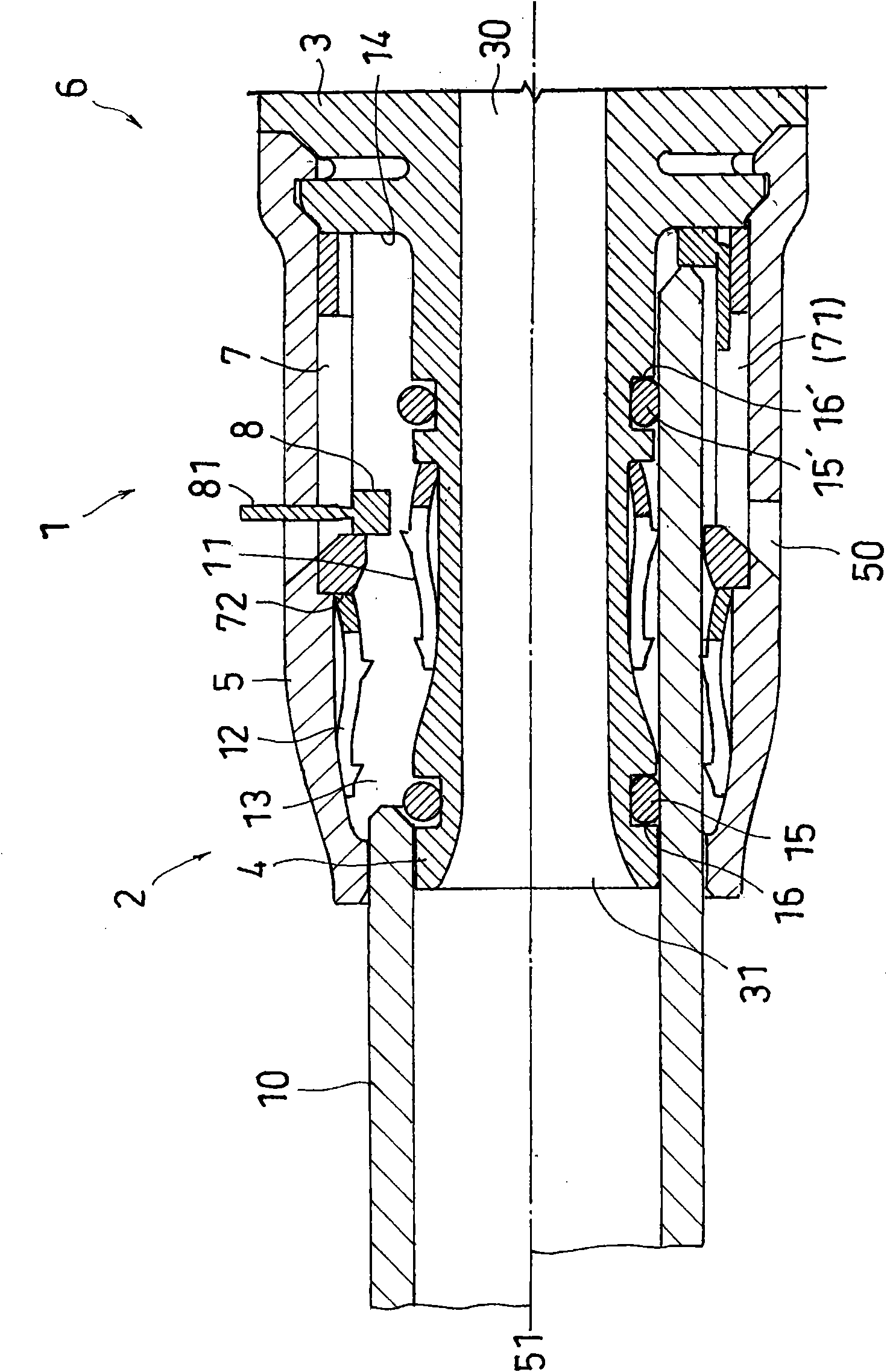
[0133] figure 1 It shows the in-line pipe joint 1 of a preferred embodiment of the present invention provided with the connecting tube insertion confirming mechanism 6, the upper half shows the state before the connecting tube is inserted, the lower half shows the state after the connecting tube is inserted, and A cross-sectional view of a case cut through a section through its central axis. refer to figure 1 It can be seen that the pipe joint 1 of the present invention only needs to include at least one connecting pipe insertion socket 2, so its overall shape is not limited to I-shape, but can also be T-shape or cross-shape.

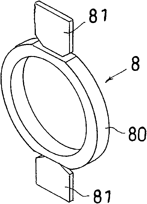
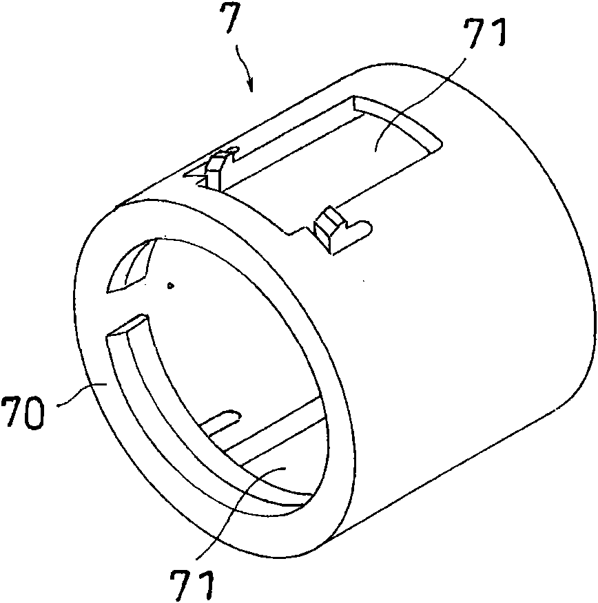
[0134] The pipe joint 1 includes a joint body 3 , an inner cylinder 4 , an outer cylinder 5 , an inner lock ring 11 and an outer lock ring 12 , and a connection tube insertion confirmation mechanism 6 , each of which has a substantially cylindrical or ring shape. In addition, in the first embodiment, the joint main body 3 includes the inner cylindrica...

Embodiment 2

[0165] Figure 10 It is an in-line connecting tube 1' according to another preferred embodiment of the present invention provided with a connecting tube insertion confirming mechanism 6. The upper half shows the state before the connecting tube is inserted, and the lower half shows the state after the connecting tube is inserted. And it shows the cross-sectional view of the case cut in the cross-section passing through the central axis. refer to Figure 10 It is understood that the pipe joint 1' of the present embodiment 2 has the same structure as the pipe joint 1 of the embodiment 1 except for the following points, the difference being that the locking ring 17 for locking the connecting pipe 10 has a radially extending A plurality of teeth or claws, and is an annular type lock ring fixed to the inner peripheral surface of the outer cylinder 5 .

[0166] Therefore, the pipe joint 1' of the second embodiment includes a joint main body 3, an inner cylinder 4, an outer cylinde...


PUM


Abstract

The invention provides a bulk type pipe joint provided with a special connecting pipe into which a confirming mechanism can be inserted, wherein the insertion of the connecting pipe and the connecting operation are simple, and the pipe joint can be used for easily and accurately grasping whether the inserted connecting pipe reaches any determined position in the pipe joint during connection. The pipe joint is characterized by being provided with a C-type annular or O-type annular part which is of a radiate extensional flexible rod-shaped part and is arranged in the accommodating part of the pipe joint. By virtue of adjusting the length of the rod-shaped part, when the connecting pipe is inserted, the annular part is pressed in an inner direction by the connecting pipe, the rod-shaped part which is previously arranged in a through hole can be pulled into an outer barrel body from the exterior of the outer barrel body, and the inserting confirming position of the length of the connecting pipe relative to the accommodating part of the pipe joint is freely changed.

Description

technical field [0001] The present invention relates to a pipe joint with a connecting pipe insertion confirming mechanism for connecting a connecting pipe in a one-touch type, in particular to a one-touch pipe joint, which has a The outer cylinder and inner cylinder of the tube receiving part, the insertion and connection operation of the connecting tube are simple, and there is a dedicated connecting tube insertion confirmation mechanism, which can accurately and easily grasp whether the inserted connecting tube reaches the pipe joint when connecting Links are made at arbitrarily determined positions. Background technique [0002] A pipe connector for connecting pipes in a push-in connection is known at present. For example, JP Unexamined Publication No. 4-18793 (Patent Document 1), JP Unexamined Publication No. 2001-193883 (Patent Document 2), and JP Unexamined Publication No. 2003-227592 (Patent Document 3) disclose an in-line The pipe joint is characterized in that a ...

Claims


Application Information

Patent Timeline
Patent Type & Authority Applications(China)
IPC IPC(8): F16L37/084
Inventor 太田浩司水野宏俊北岛典和中居义贵长谷川博一
Owner ARONKASEI
Why Eureka
Try Eureka