Cooling system for internal combustion engine

A technology of cooling system and internal combustion engine, applied in the direction of internal combustion piston engine, charging system, combustion engine, etc., can solve problems such as increasing fuel consumption, and achieve the effects of optimizing cooling, improving accuracy and ensuring dosing accuracy.

Inactive Publication Date: 2019-12-27
ROBERT BOSCH GMBH
View PDF0 Cites 0 Cited by
  • Summary
  • Abstract
  • Description
  • Claims
  • Application Information

AI Technical Summary

Problems solved by technology

However, at an operating point with a high load, such an internal combustion engine cannot be operated at an optimum operating point with regard to its consumption, since the operation is limited not only by the tendency to knock but also by the high exhaust gas temperature of the internal combustion engine.
One measure for reducing the tendency to knock is to adjust the ignition retardation, thereby increasing fuel consumption with the same required engine power
In order to reduce the exhaust gas temperature, it is also known to achieve a rich combustion (Anfettung) of the mixture by increasing the amount of fuel, which also increases fuel consumption

Method used


Image

  • Cooling system for internal combustion engine
  • Cooling system for internal combustion engine
  • Cooling system for internal combustion engine

Examples


Embodiment Construction

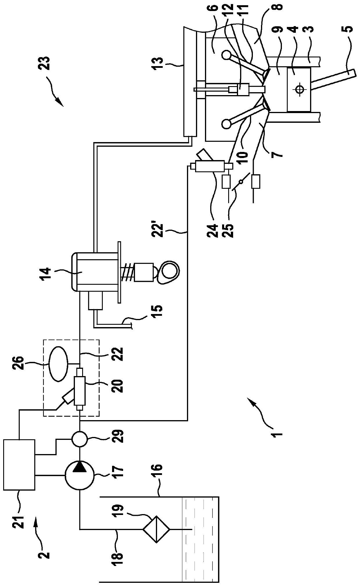
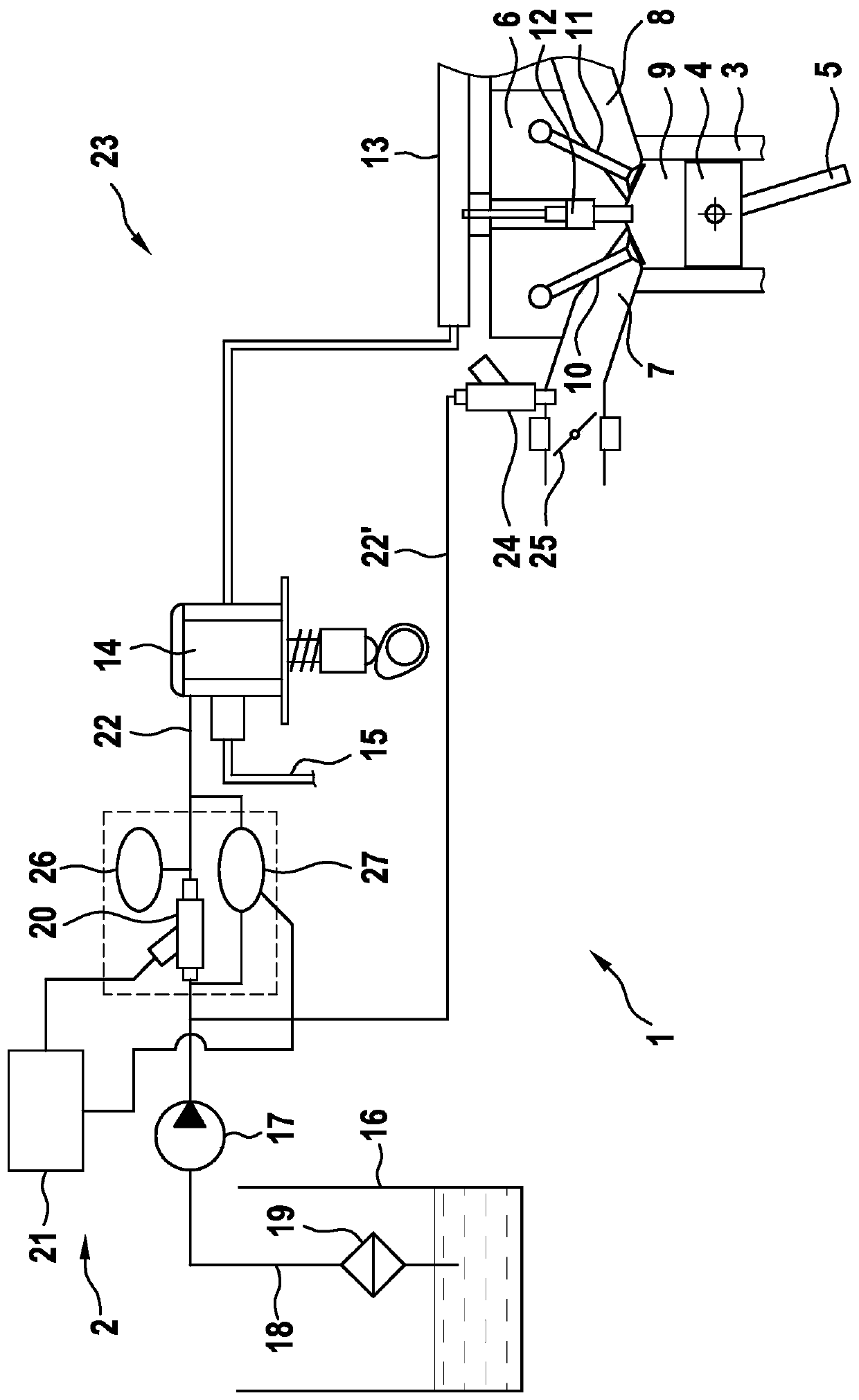
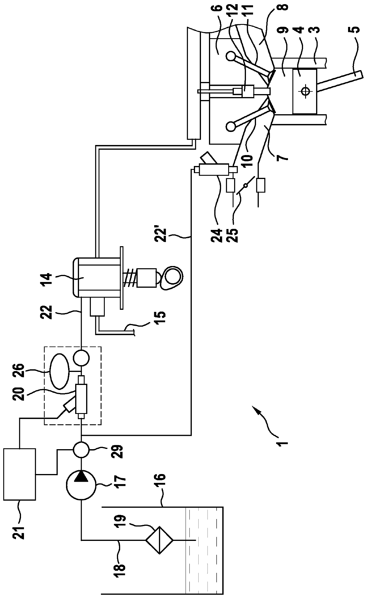
[0020] figure 1 A simplified illustration of an internal combustion engine 1 with an advantageous cooling system 2 is shown. Internal combustion engine 1 has a plurality of cylinders 3 , in each of which a piston 4 is mounted so as to be displaceable in the longitudinal direction and is coupled to a crankshaft via a connecting rod 5 . The individual cylinders 3 are closed by a cylinder head 6 , through which an inlet duct 7 and an outlet duct 8 lead into a combustion chamber 9 formed in each case by the cylinder 3 , cylinder head 6 and piston 4 . The inlet channel 7 and the outlet channel 8 are each associated with an actuable inlet valve 10 or outlet valve 11 . Furthermore, the cylinder heads 6 assigned to each of the cylinders 3 each have an injection valve 12 which, according to the exemplary embodiment, is connected to a high-pressure rail 13 for fuel injection. A high-pressure pump 14 is arranged upstream of the high-pressure rail 13 . The high-pressure pump 14 is conn...


PUM


Abstract

The invention relates to a cooling system (2) for an internal combustion engine (1), in particular an internal combustion engine of a motor vehicle, the cooling system comprising: at least one injection valve (12) for fuel associated with the internal combustion engine (1); at least one high-pressure pump (14) arranged in front of the injection valve (12) for conveying fuel to the injection valve(12); and a water injection device (23) having a dosing valve (20) arranged in front of the high-pressure pump (14) for dosing water into the fuel: arranged in such a way that the dosing valve (20) isassigned at least one pressure damper (26).

Description

technical field [0001] The invention relates to a cooling system for an internal combustion engine, in particular an internal combustion engine of a motor vehicle, having at least one injection valve for fuel associated with the internal combustion engine; at least one injection valve arranged upstream of the injection valve a high-pressure pump for delivering fuel to the injection valve; and a water injection device having a metering valve arranged upstream of the high-pressure pump for metering water into the fuel. Background technique [0002] Cooling systems of the type mentioned at the outset are known from the prior art. The requirements placed on internal combustion engines of motor vehicles with regard to the emission of harmful substances continue to increase. CO 2 Emissions in particular should be further reduced, so internal combustion engines are increasingly optimized with regard to their consumption. For this purpose, it is known, for example, to increase th...

Claims


Application Information

Patent Timeline
Patent Type & Authority Applications(China)
IPC IPC(8): F02M25/025F02M25/028
CPCF02M25/0221F02M25/025F02M25/028F02M25/0228Y02T10/12
Inventor P·格拉代尔P·申克
Owner ROBERT BOSCH GMBH
Why Eureka
Try Eureka