

Pneumatic pipeline internal traveling device
A technology of pneumatic pipelines and walkers, which is applied in the direction of pipe components, pipes/pipe joints/fittings, mechanical equipment, etc., and can solve problems such as low safety and poor reliability
- Summary
- Abstract
- Description
- Claims
- Application Information
AI Technical Summary
Problems solved by technology
Method used
Image

Examples
Embodiment Construction
[0019] The present invention will be further described below in conjunction with the accompanying drawings.
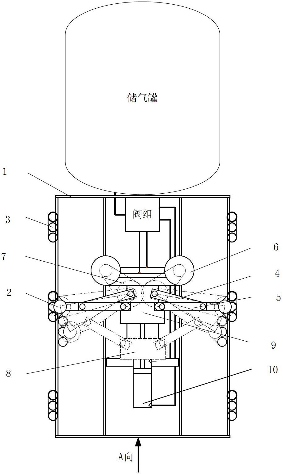
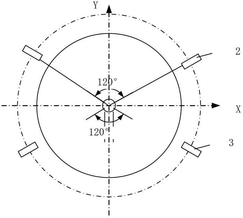
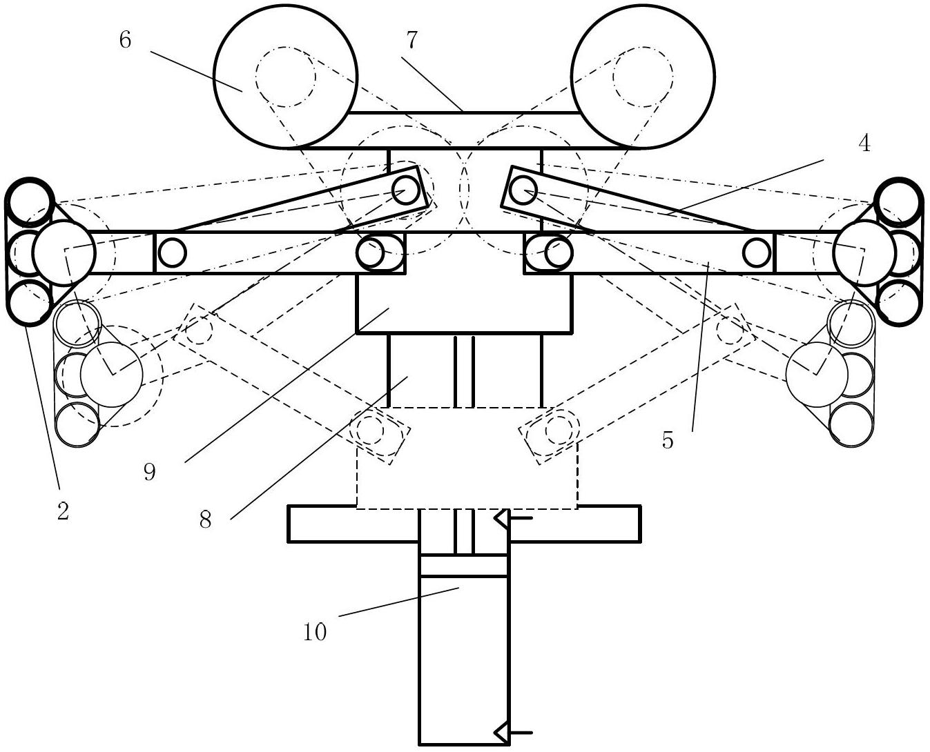
[0020] refer to Figure 1 ~ Figure 4 , a walking device in a pneumatic pipeline, comprising a vehicle frame 1, a driving wheel 2 and a walking wheel 3, two walking wheels 2, a driving wheel 3 and two walking wheels are arranged in sequence along the central axis direction of the vehicle frame on the vehicle frame 1 Wheel 2, viewed from the axial direction, the walking wheel 3 is located in the lower semicircle of the frame, and the driving wheel 2 is located in the upper semicircle of the frame; the radial distribution is two traveling wheels 3 that are symmetrical about the Y axis, and the traveling wheel 3 is installed on the frame 1 Above, the drive wheel 2 is connected to the transmission mechanism, and the transmission mechanism includes a support arm 4, a drive arm 5, a vehicle frame central shaft 8 and a sliding sleeve 9, and the drive wheel 3 is installed on on...
PUM
| Property | Measurement | Unit |
|---|---|---|
| Angle | aaaaa | aaaaa |
Abstract
Description
Claims
Application Information