Eureka AIR delivers breakthrough ideas for toughest innovation challenges, trusted by R&D personnel around the world.

Pneumatic-crawler traveling mechanism in pipeline

A walking mechanism and crawler-type technology, which is applied in the direction of motor vehicles, pipe components, mechanical equipment, etc., can solve problems such as poor climbing ability, and achieve the effects of increasing adhesion coefficient, large traction force, and increasing contact area

Active Publication Date: 2014-03-26
THE NORTHERN RES INST OF NJUST
View PDF5 Cites 0 Cited by
  • Summary
  • Abstract
  • Description
  • Claims
  • Application Information

AI Technical Summary

Problems solved by technology

[0003] In order to overcome the shortcomings of the poor climbing ability of the existing in-pipeline walker, the present invention provides a pneumatic crawler-type in-pipeline walking mechanism that improves the climbing ability

Method used


Image

  • Pneumatic-crawler traveling mechanism in pipeline
  • Pneumatic-crawler traveling mechanism in pipeline
  • Pneumatic-crawler traveling mechanism in pipeline

Examples


Embodiment Construction

[0032] The present invention will be further described below in conjunction with the accompanying drawings.

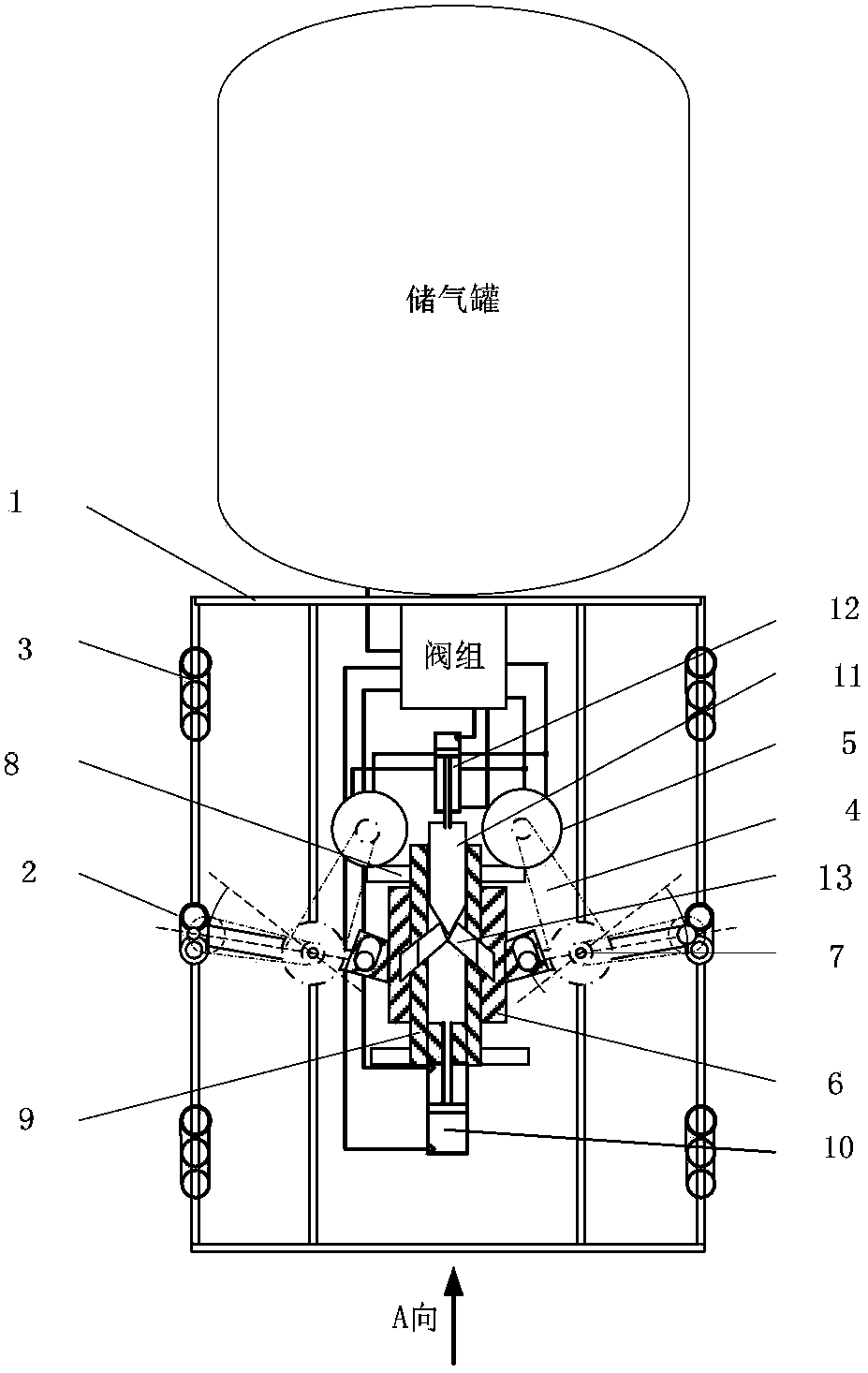
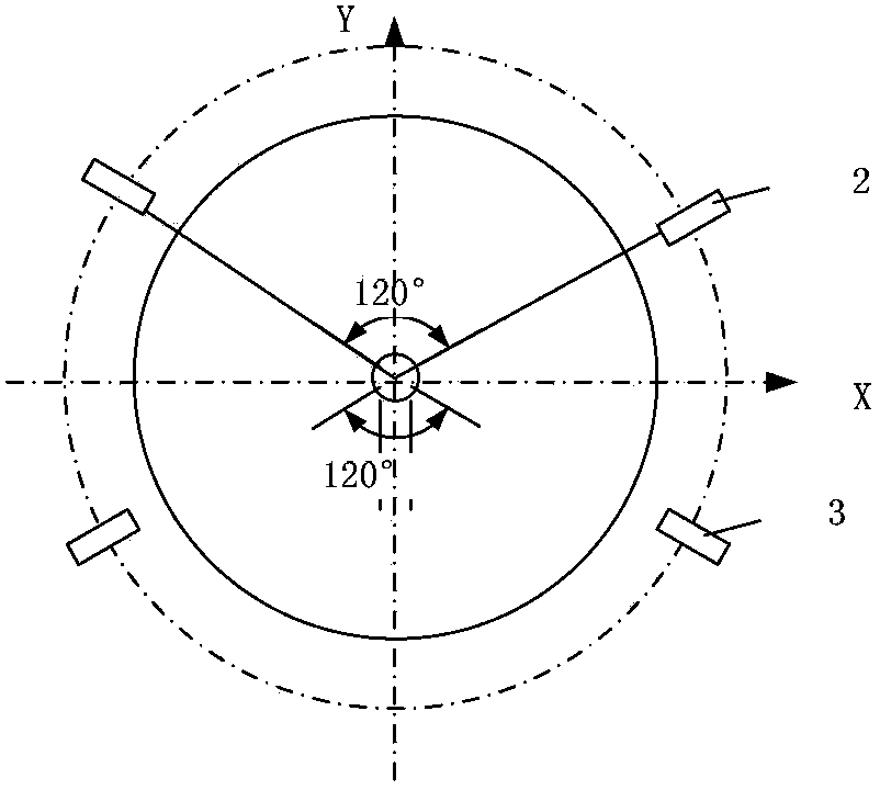
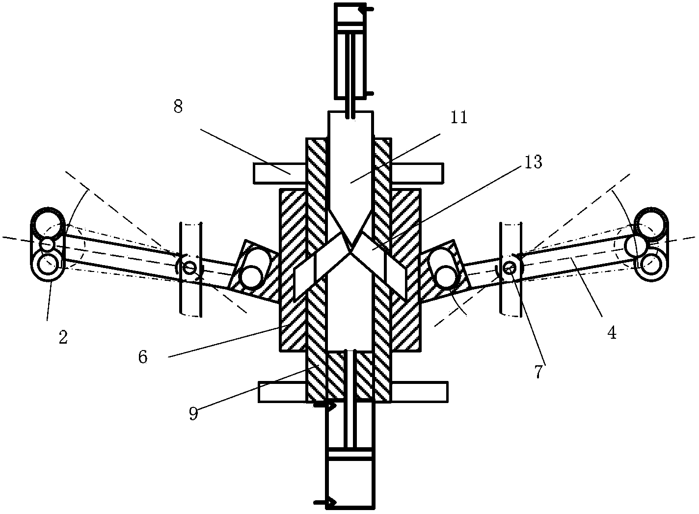
[0033] refer to Figure 1 to Figure 14 , a pneumatic crawler-type pipeline inner walking mechanism, comprising a vehicle frame 1, a driving wheel 2 and a driving wheel 3, two driving wheels 3, a driving wheel 2 and two A walking wheel 3, viewed from the axial direction, the walking wheel 3 is located in the lower semicircle of the vehicle frame, and the driving wheel 2 is located in the upper semicircle of the vehicle frame; the radial distribution is two traveling wheels that are symmetrical about the Y axis, and the traveling wheel 3 is installed on the vehicle frame 1, the drive wheel 2 is connected to the transmission mechanism, and the transmission mechanism includes a support arm 4, a sliding sleeve 6 and a frame center shaft 9. The drive wheel 2 is installed on one end of the support arm 4 through a pin shaft, and the support arm 4 The other end of the support ...


PUM


Abstract

The invention relates to a pneumatic-crawler traveling mechanism in a pipeline, which comprises a frame, driving wheels and traveling wheels, wherein two traveling wheels, the driving wheels and two traveling wheels are arranged on the frame orderly along a central shaft of the frame; looked from an axial direction, the traveling wheels are located on a low semi-circle of the frame; the driving wheels are located on an upper semi-circle of the frame; two traveling wheels are distributed on a radial direction symmetrically around a Y axle; the traveling wheels are mounted on the frame; the driving wheels are mounted on one end of a support arm through a pin shaft; the other end of the support arm is linked to a sliding sleeve through a hinge; the support arm can be rotationally mounted on a gyrating shaft; a central shaft base is fixedly connected with a frame central shaft; the sliding sleeve can be sleeved on the frame central shaft in a sliding manner; the sliding sleeve is connected with a first driving air cylinder; an air motor is mounted on a machine frame; chain wheels are mounted on an air motor shaft, the gyrating shaft and driving wheel shafts; and power is transmitted from the air motor to the driving wheels. According to the invention, crawler wheels are used, so that positive pressure of the driving wheels, the travelling wheels and a pipeline wall is improved; and the pneumatic-crawler traveling mechanism is adapted to travel in a large-gradient pipeline.

Description

technical field [0001] The invention relates to a walking mechanism in a pipeline. Background technique [0002] The sealing of the pipeline and the working environment determine the difficulty of pipeline construction. Pipeline robot is an essential tool in pipeline construction. Today, through the efforts of scholars from various countries, various pipeline robots have emerged. From the structural point of view, it is mainly divided into wheeled pipeline robots, footed pipeline robots, crawler pipeline robots and peristaltic pipeline robots. Wheeled pipeline robots are usually pneumatic. Japan's Toshiba Corporation developed the first wheeled pipeline robot in 1997. In order to increase traction, the robot adopted multi-wheel drive, but the wheel diameter was too small, the ability to overcome obstacles was limited, and the structure was complicated; developed by Werner Neubern et al. There are three types of spider-type micro-pipe robots with 3, 6, and 8 legs. The pri...

Claims


Application Information

Patent Timeline
Patent Type & Authority Patents(China)
IPC IPC(8): B62D57/02F16L55/32F16L55/38
Inventor 邢彤孟彬
Owner THE NORTHERN RES INST OF NJUST
Why Eureka
Eureka Blog
Learn More