
Bumper structure for vehicle

A bumper and bumper beam technology, applied to bumpers, vehicle parts, vehicle safety arrangements, etc., can solve problems such as long stroke, increased crushing margin of safety plate, and overall length elongation

Inactive Publication Date: 2012-09-26
HONDA MOTOR CO LTD
View PDF7 Cites 5 Cited by
  • Summary
  • Abstract
  • Description
  • Claims
  • Application Information

AI Technical Summary

Problems solved by technology

[0006] However, in Patent Documents 1 and 2, it is necessary to increase the crushing margin of the safety plate in order to absorb the impact.
That is, the amount of travel from the bumper beam to the front of the safety panel is longer, resulting in an overall elongation of the vehicle

Method used


Image

  • Bumper structure for vehicle
  • Bumper structure for vehicle
  • Bumper structure for vehicle

Examples


Embodiment

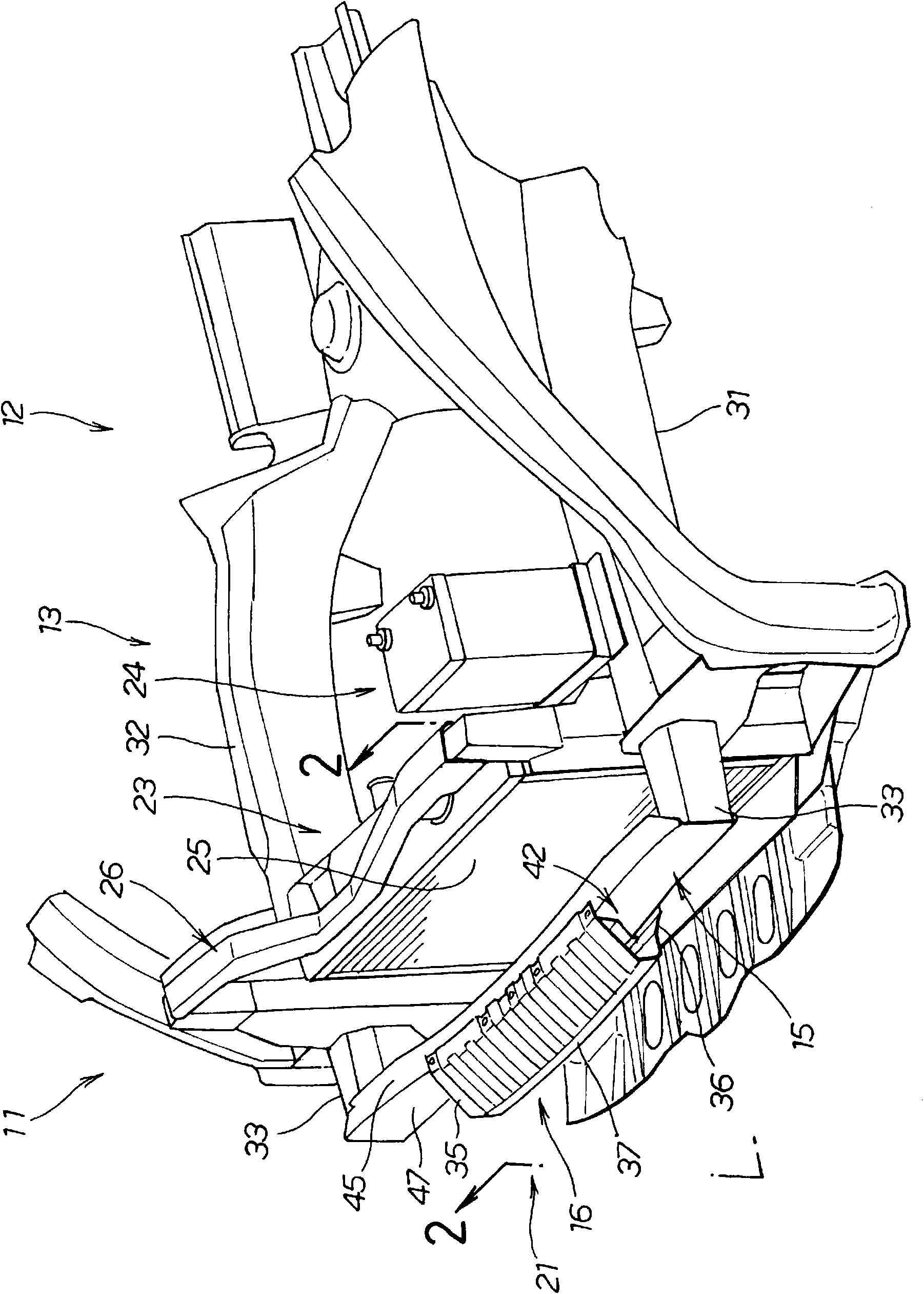
[0034] Such as figure 1 As shown, the vehicle body front structure (bumper structure) of the present embodiment is used for the structure of the front portion (front body) 13 of the vehicle body 12 of the vehicle 11 as an obstacle countermeasure.

[0035] In the illustrated embodiment, a front bumper 21 is shown that absorbs the impact generated when the vehicle 11 has a frontal collision.

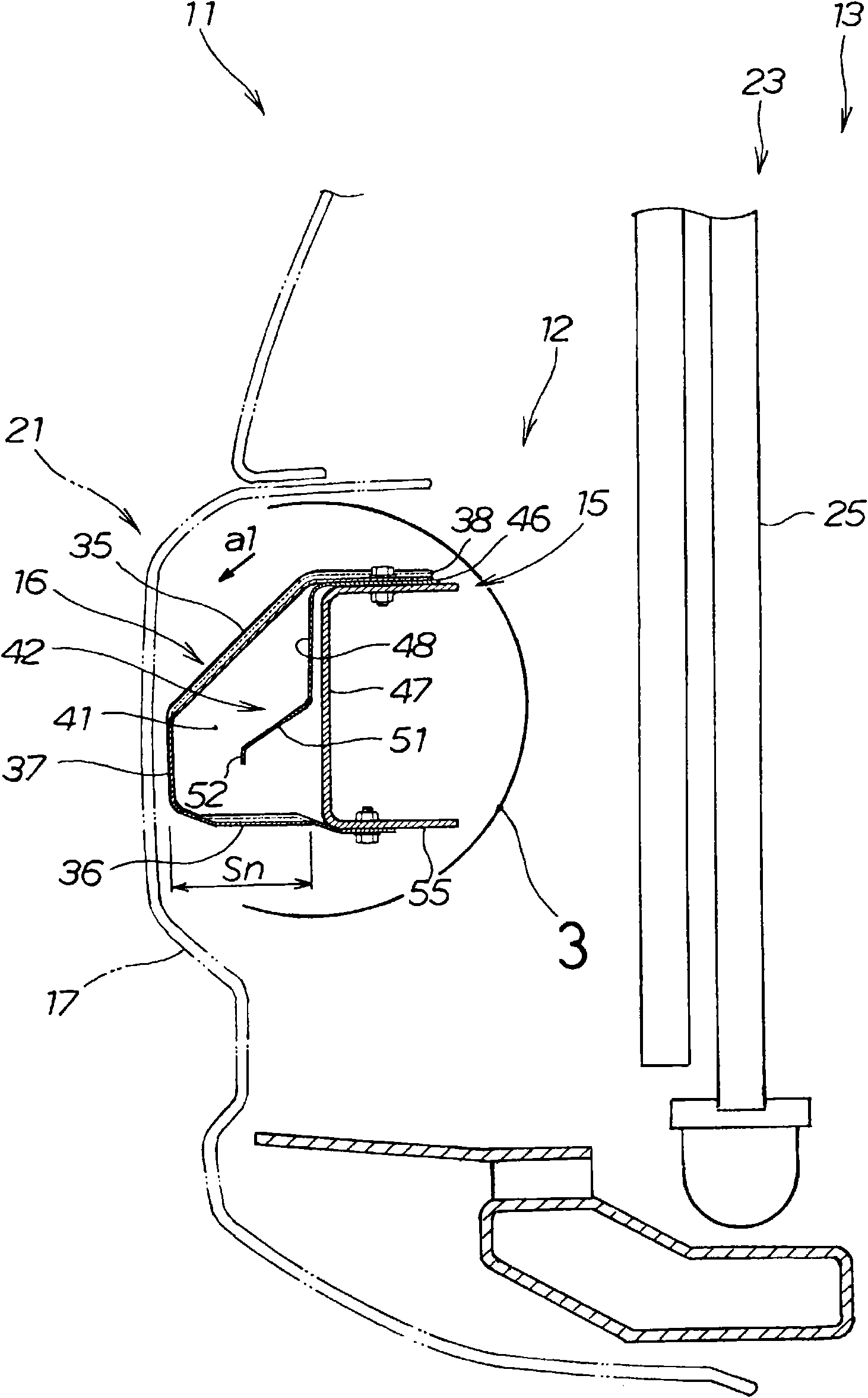
[0036] Such as figure 1 , figure 2 As shown in the bumper structure, a bumper beam (front bumper beam) 15 on the front side of the vehicle 11 is equipped with a safety plate 16 for shock absorption, and is formed by a bumper face 17 forming a part of the design of the front side of the vehicle 11. This safety plate 16 is covered.

[0037] The vehicle 11 has: a front bumper 21 ; a cooling device 23 for cooling the engine; and a battery 24 . The cooling device 23 has a heat exchange device 25 disposed on the rear side of the front bumper 21 . The heat exchange device 25 is fixed to the...


PUM


Abstract

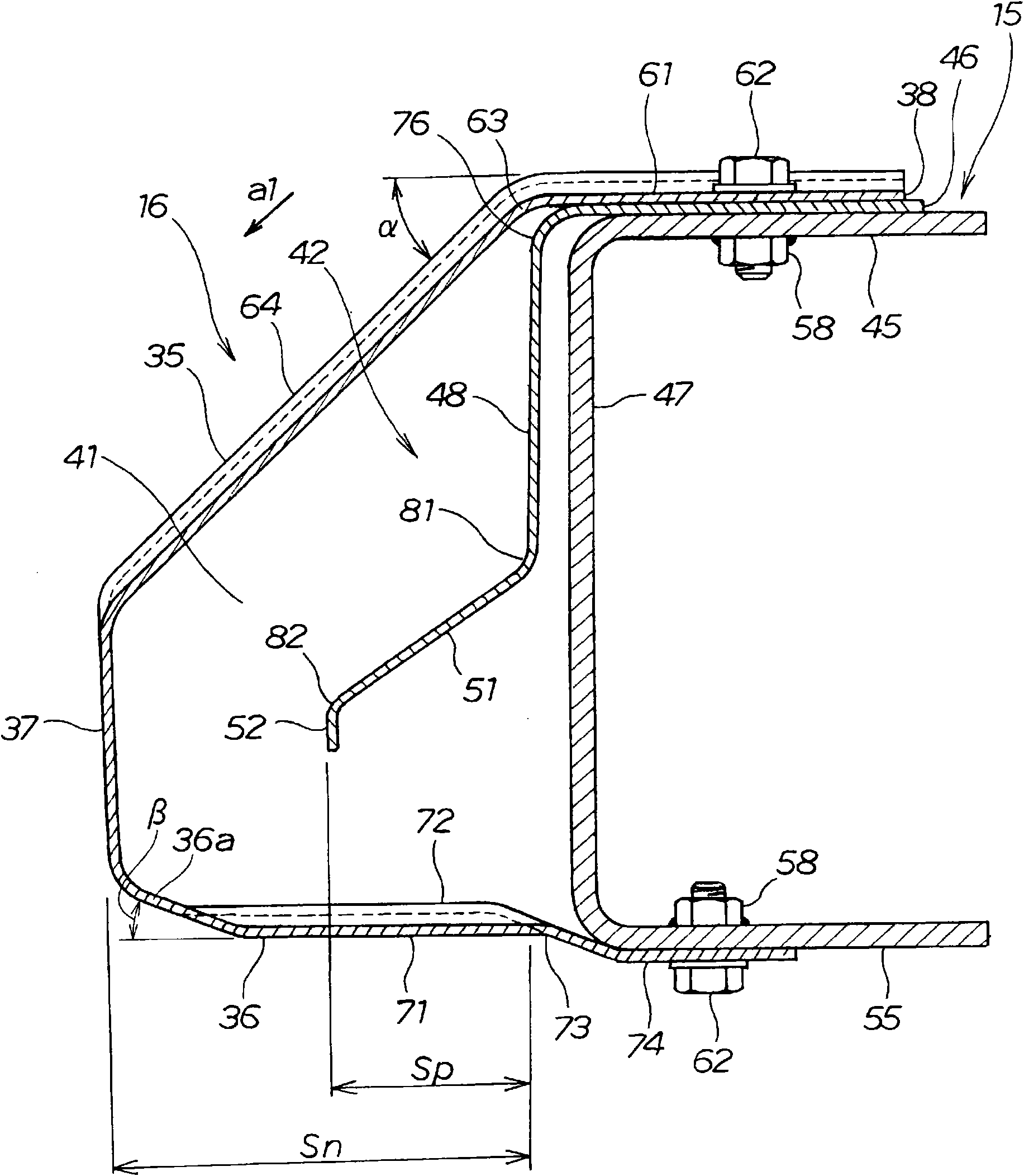
Disclosed is a bumper structure equipped with an inner plate (42) in a hollow section (41) formed by a bumper beam (15) and a safety plate (16). The safety plate (16) comprises a top plate (35), a bottom plate (36), and a load input plate (37) connecting both. The inner plate (42) comprises a mounted section (46) that is mounted to the bumper beam (15), a leg section (48) that continues from the mounted section (46) and extends downward, a back support section (51) that continues from the leg section (48) and is approximately parallel to the top plate (35), and a load input flange (52) that continues from the back support section (51).

Description

technical field [0001] The present invention relates to bumper constructions that absorb impacts, for example, in a vehicle frontal collision. Background technique [0002] There is a bumper structure in which when a vehicle collides with an impact object, the inside of the bumper is deformed to absorb the impact. [0003] For example, the bumper structure includes, in order from the front: a bumper face; a safety panel covered by the bumper face; and a bumper beam that supports the safety panel and extends in the vehicle width direction. [0004] The safety panel is installed in the bumper beam in a substantially U-shaped cross-section with the opening fitted in the opening. In addition, a deformation guide portion serving as a starting point of deformation is provided on the lower portion attached to the lower portion of the bumper beam, whereby the safety panel is completely crushed when absorbing the impact (for example, refer to Patent Document 1 ). [0005] In addit...

Claims


Application Information

Patent Timeline
Patent Type & Authority Applications(China)
IPC IPC(8): B60R19/18
CPCB60R19/18B60R2019/186
Inventor 露崎匠石园学池鲤鲋贵今泉岩菊池裕二
Owner HONDA MOTOR CO LTD
Learn More