Tin wire punching device

A punching device and tin wire technology, which is applied in the direction of tin feeding device, auxiliary device, metal processing equipment, etc., can solve the problems of easy bending, winding, and easy slipping of tin wire, etc., to achieve increased friction, low investment cost, The effect of low equipment investment cost

Active Publication Date: 2015-12-09
QUICK INTELLIGENT EQUIP CO LTD
View PDF5 Cites 0 Cited by
  • Summary
  • Abstract
  • Description
  • Claims
  • Application Information

AI Technical Summary

Problems solved by technology

[0004] The technical problem to be solved by the present invention is: in order to solve the technical problems that the tin wire is easy to slip, easy to bend, and entangled when it is conveyed, the invention provides a tin wire punching device, which realizes the automatic and continuous output of tin wires of different specifications, And it solves the problem of automatic and continuous tin breaking of tin wires of different specifications

Method used


Image

  • Tin wire punching device
  • Tin wire punching device
  • Tin wire punching device

Examples


Embodiment 1

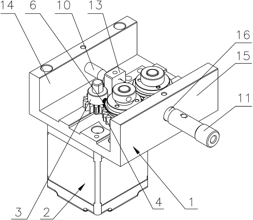
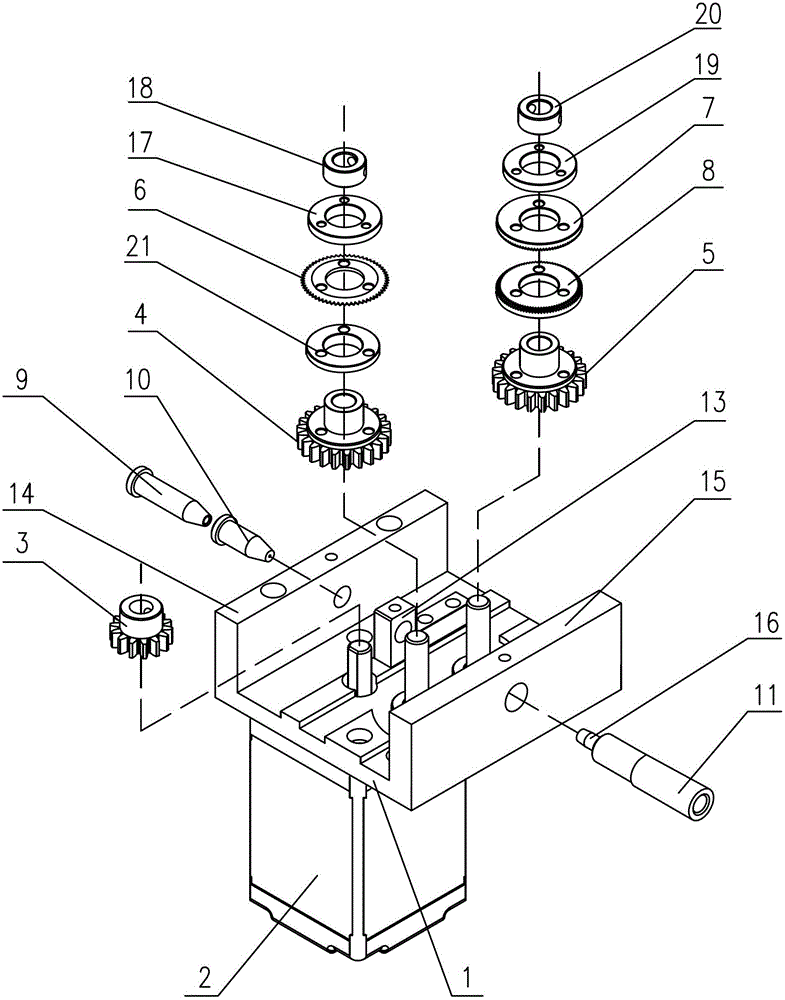
[0025] This embodiment is applied to models with pulse adjustment, such as Figure 1~2 As shown, the tin wire punching device of the present invention has a main support plate 1, a driving motor 2 is installed on the main support plate 1, a driving gear 3 is installed on the output shaft of the driving motor 2, and the driving gear 3 is meshed with a first driven Gear 4, the first driven gear 4 meshes with the second driven gear 5, the first driven gear 4 and the second driven gear 5 are located on the plate surface of the main support plate 1, the first driven gear 4 is the same as The shaft is equipped with a saw wheel 6 with evenly distributed serrations in the circumferential direction. The teeth of the saw wheel 6 of the present invention are in a V-shaped sawtooth shape, and its tooth width matches the diameter of the tin wire. The saw wheel 6 and the first driven gear 4 are also coaxial. The supporting wheel 21 is installed, the first pinch wheel 17 is installed coaxial...

Embodiment 2

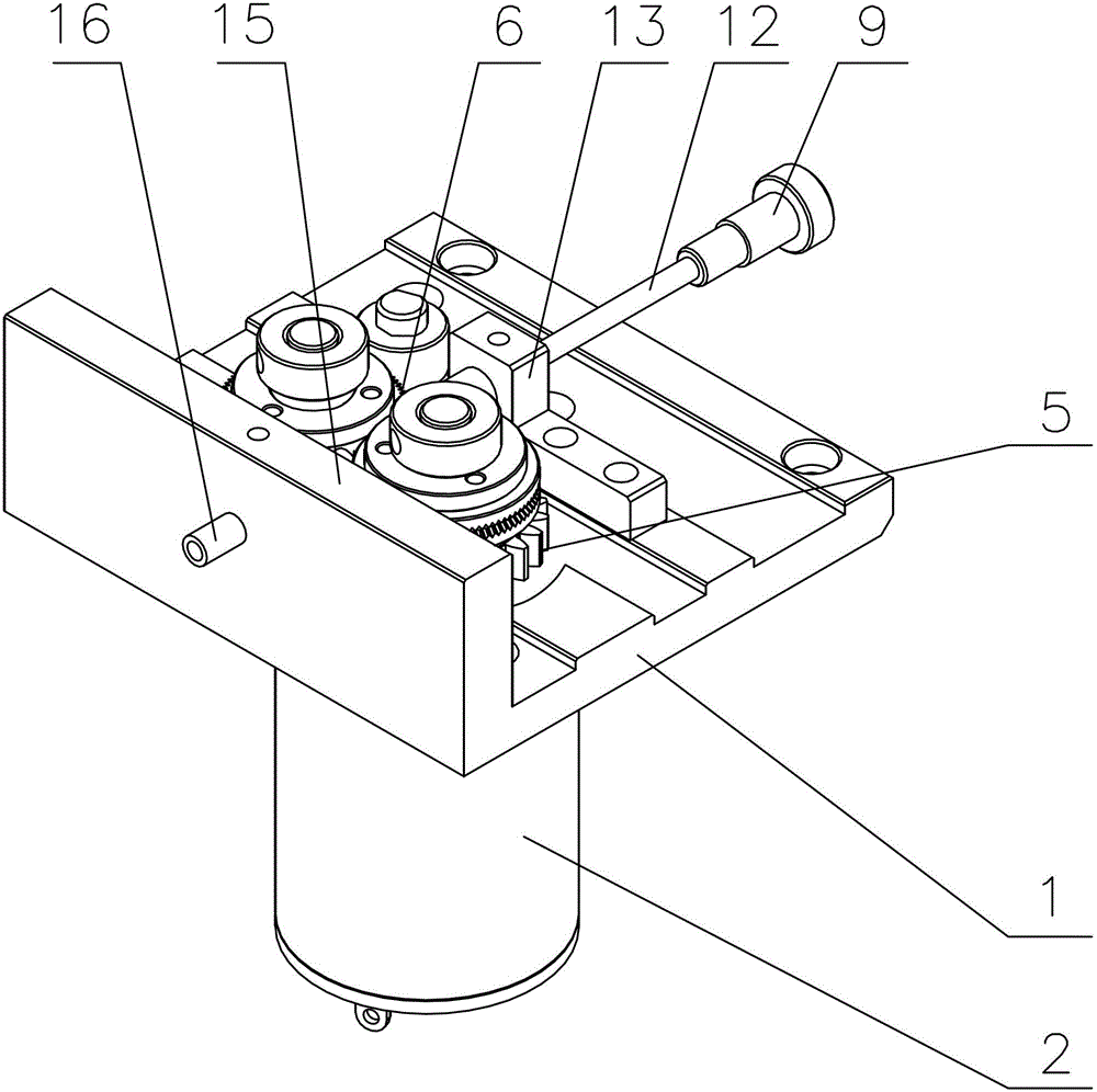
[0033] Such as Figure 3~4 As shown, the difference between this embodiment and Embodiment 1 is that this embodiment is applied to a model with voltage and speed regulation. In this embodiment, only one end of the main support plate 1 has a boss, that is, the wire outlet fixing boss 15, correcting The complete set includes tin-in positioning sleeve 9, tin-in guide tube 12, tin wire correction nozzle 10 and tin outlet head 16, tin-in positioning sleeve 9 is connected to tin-in guide tube 12, tin-in guide tube 12 is connected to tin wire correction Nozzle 10, the tin wire straightening mouth 10 is installed on the wire feeding direction of the main support plate 1, the wire outlet end of the tin wire straightening mouth 10 is pierced with a tin feeding positioning bracket 13, and its mouth is close to the saw wheel 6 side, and the tin wire feeding Positioning bracket 13 is fixedly connected on the plate surface of main support plate 1, and tin head 16 is installed on the fixed b...


PUM


Abstract

The invention relates to a punching device of a tin wire. The punching device comprises a main supporting plate, wherein a drive motor is arranged on the main supporting plate; a drive gear is arranged on an output shaft of the drive motor; a first driven gear is meshed on the drive gear; a second driven gear is meshed on the first driven gear; the first driven gear and the second driven gear are arranged on the panel of the main supporting plate; a saw wheel which is uniformly distributed with sawteeth on the periphery is coaxially arranged on the first driven gear; a cone pulley assembly with an annular tooth socket is arranged on the second driven gear; the annular tooth socket and the saw wheel are located on the same plane; the cone pulley assembly and the second driven gear are coaxially arranged; and the main supporting plate is provided with complete correcting equipment for locating and correcting the tin wire. With the adoption of the punching device disclosed by the invention, the cone pulley assembly and the saw wheel can be detachably exchanged; the device has low investment cost; the friction force is increased by the annular tooth socket; the tin wire does not easily slip and does not deform; and straightness of the tin wire without bending can be kept by a tin wire correcting nozzle.

Description

technical field [0001] The invention belongs to the technical field of soldering equipment, in particular to a tin wire punching device. Background technique [0002] Generally speaking, the process of breaking tin includes the automatic input and output of tin wire and the automatic transportation during the process of breaking tin, and it is necessary to ensure the continuity of the automatic wire output during the drilling process. The existing tin-breaking and punching device generally punches the tin wire through the saw wheel with sawtooth around it or slots the tin wire through the blade, and makes spaced holes or a groove on the tin wire to make the flux Released during the process to prevent flux splashing and solder balls caused by "tin explosion", thus avoiding the pollution and poor contact of many electronic components, especially sensitive components. [0003] The patent application number is 200820210574.1. In the disclosed technical solution, the tin wire is...

Claims


Application Information

Patent Timeline
Patent Type & Authority Patents(China)
IPC IPC(8): B23K3/08B23K3/06
Inventor 戚国强周冬林姜加伟
Owner QUICK INTELLIGENT EQUIP CO LTD
Why Eureka
Try Eureka