Punching device of tin wire
A technology of punching device and tin wire, applied in tin feeding device, auxiliary device, metal processing equipment and other directions, can solve the problems of easy bending, winding, and tin wire slipping, etc., to increase friction, low investment cost, The effect of low investment cost of equipment
- Summary
- Abstract
- Description
- Claims
- Application Information
AI Technical Summary
Problems solved by technology
Method used
Image
Examples
Embodiment 1
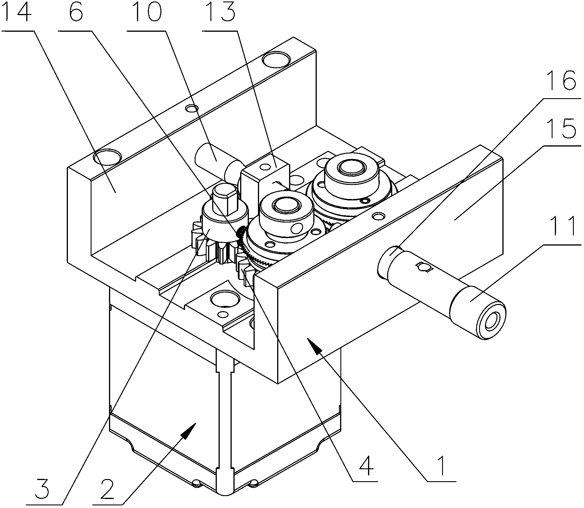
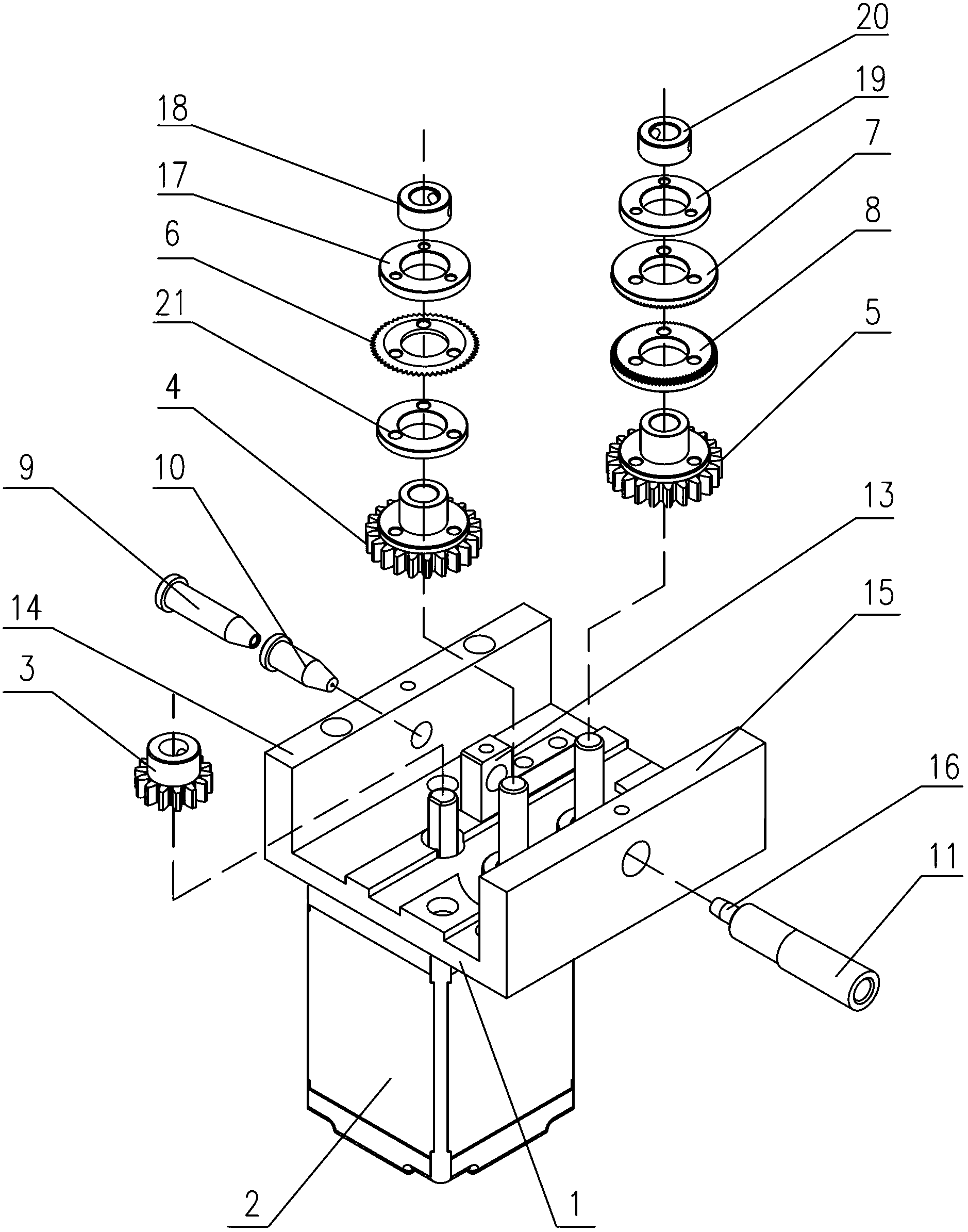
[0025] This embodiment is applied to models with pulse adjustment, such as Figure 1~2 As shown, the tin wire punching device of the present invention has a main support plate 1, a driving motor 2 is installed on the main support plate 1, a driving gear 3 is installed on the output shaft of the driving motor 2, and the driving gear 3 is meshed with a first driven Gear 4, the first driven gear 4 meshes with the second driven gear 5, the first driven gear 4 and the second driven gear 5 are located on the plate surface of the main support plate 1, the first driven gear 4 is the same as The shaft is equipped with a saw wheel 6 with evenly distributed serrations in the circumferential direction. The teeth of the saw wheel 6 of the present invention are in a V-shaped sawtooth shape, and its tooth width matches the diameter of the tin wire. The saw wheel 6 and the first driven gear 4 are also coaxial. The supporting wheel 21 is installed, the first pinch wheel 17 is installed coaxial...
Embodiment 2
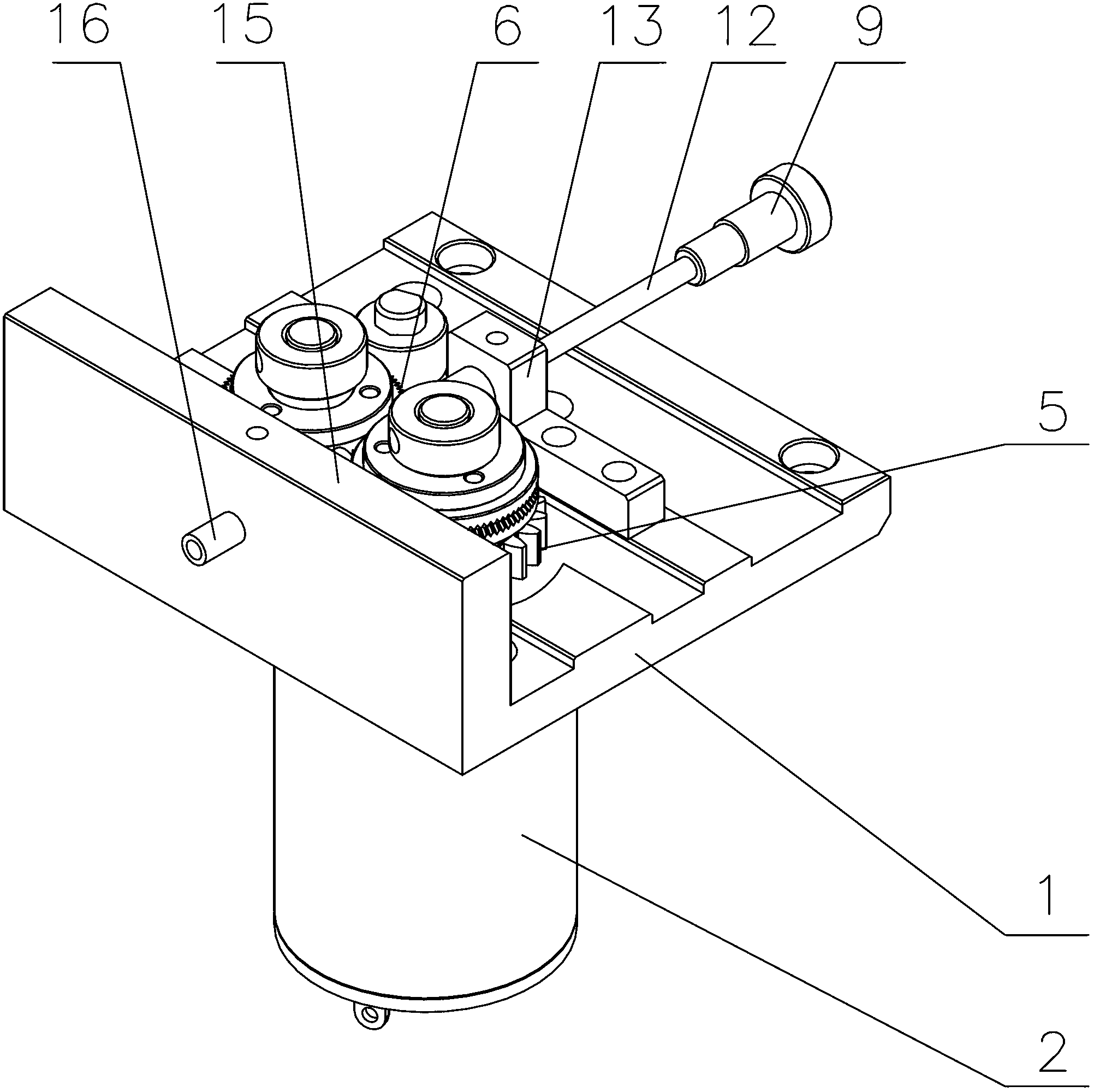
[0033] like Figure 3~4 As shown, the difference between this embodiment and Embodiment 1 is that this embodiment is applied to a model with voltage and speed regulation. In this embodiment, only one end of the main support plate 1 has a boss, that is, the wire outlet fixing boss 15, correcting The complete set includes tin-in positioning sleeve 9, tin-in guide tube 12, tin wire correction nozzle 10 and tin outlet head 16, tin-in positioning sleeve 9 is connected to tin-in guide tube 12, tin-in guide tube 12 is connected to tin wire correction Nozzle 10, the tin wire straightening mouth 10 is installed on the wire feeding direction of the main support plate 1, the wire outlet end of the tin wire straightening mouth 10 is pierced with a tin feeding positioning bracket 13, and its mouth is close to the saw wheel 6 side, and the tin wire feeding Positioning bracket 13 is fixedly connected on the plate surface of main support plate 1, and tin head 16 is installed on the fixed boss...
PUM
 Abstract
Description
Claims
Application Information
 - R&D
- Intellectual Property
- Life Sciences
- Materials
- Tech Scout
- Unparalleled Data Quality
- Higher Quality Content
- 60% Fewer Hallucinations
Browse by: Latest US Patents, China's latest patents, Technical Efficacy Thesaurus, Application Domain, Technology Topic, Popular Technical Reports.
© 2025 PatSnap. All rights reserved.Legal|Privacy policy|Modern Slavery Act Transparency Statement|Sitemap|About US| Contact US: help@patsnap.com


