
Method for desulfurizing and denitrating smoke simultaneously through ammonia method

A technology for desulfurization, denitrification and flue gas is applied in the field of environmental protection, which can solve the problems of difficult operation and operation, complex structure and high cost, and achieve the effects of simple process and system, simplified process flow and small investment.

Active Publication Date: 2011-01-05
NANJING NEW CENTURY JIANGNAN ENVIRONMENTAL PROTECTION CO LTD
View PDF3 Cites 71 Cited by
  • Summary
  • Abstract
  • Description
  • Claims
  • Application Information

AI Technical Summary

Problems solved by technology

[0006] In order to solve the above problems, the patent CN2712446 proposed a multi-stage serial ammonia desulfurization and denitrification device, which has a complex structure and difficult operation; the patent CN101053747 proposed a method of first oxidizing NO in the flue gas, and then using ammonia to absorb The desulfurization and denitrification process requires a large amount of hydrogen peroxide, ozone and other oxidants
At the same time, the above-mentioned processes and devices all need to consume ammonia during denitrification, and the cost is relatively high.

Method used


Image

  • Method for desulfurizing and denitrating smoke simultaneously through ammonia method
  • Method for desulfurizing and denitrating smoke simultaneously through ammonia method

Examples


Embodiment 1

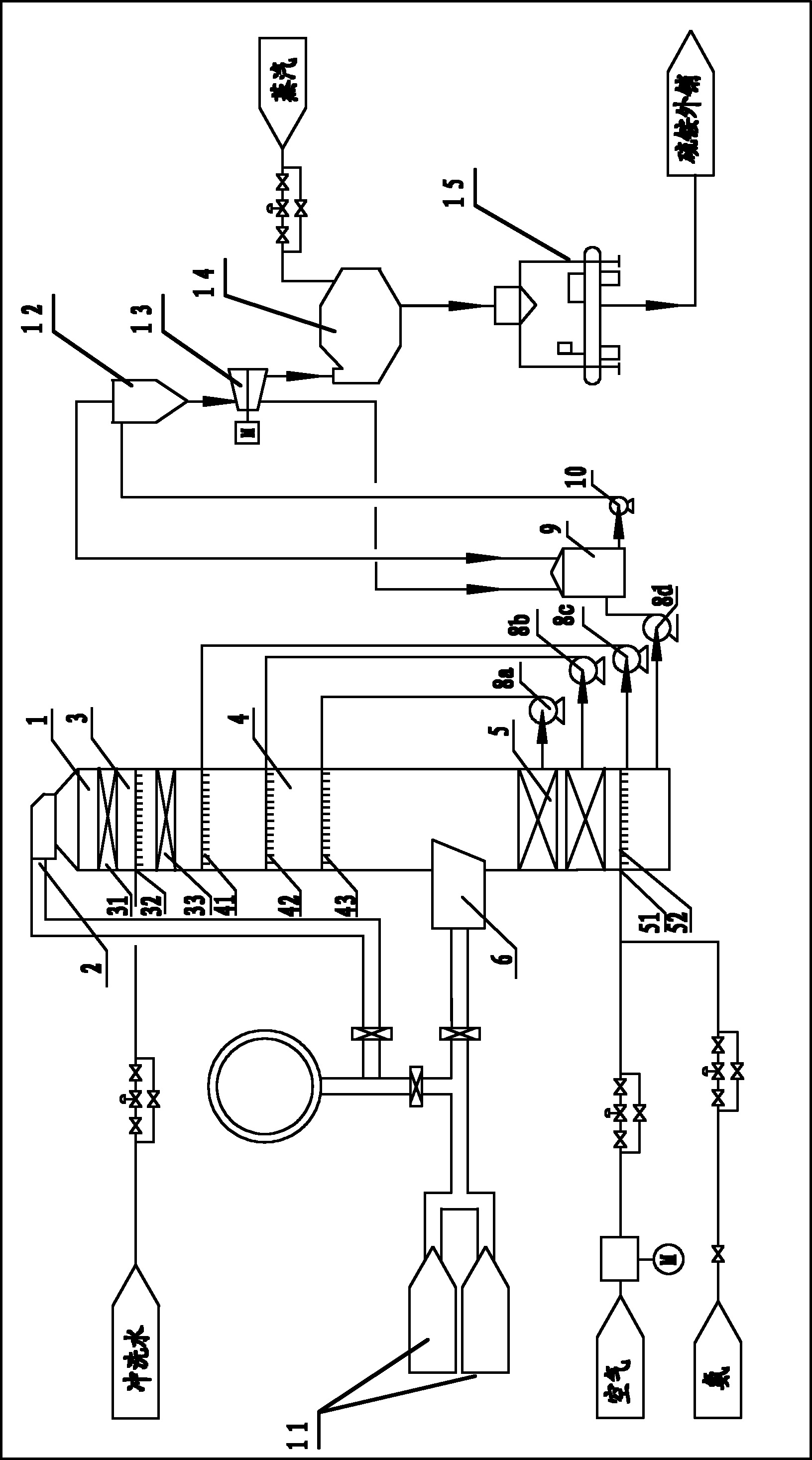
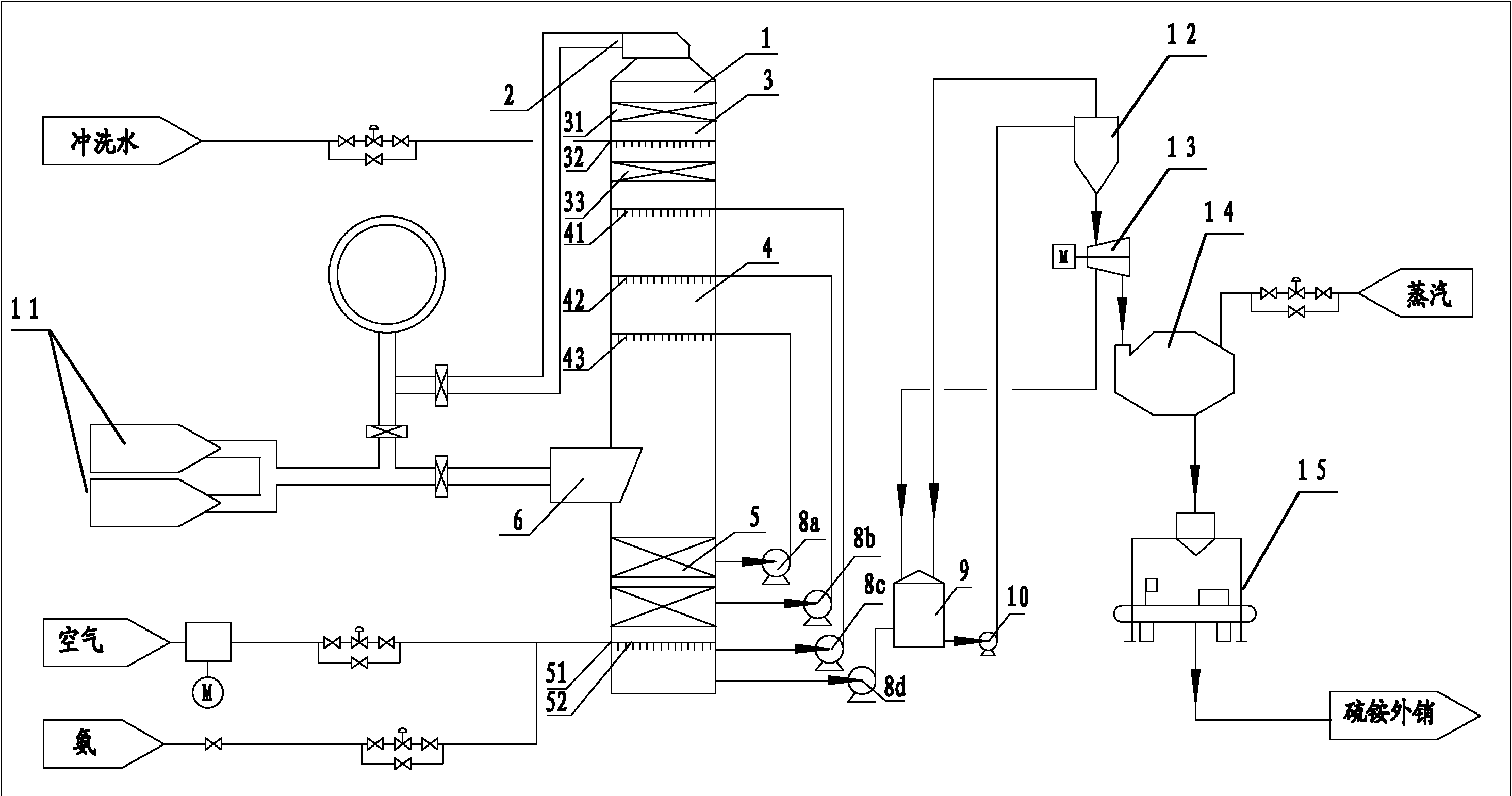
[0048] like figure 1 As shown, the flue gas transported by the induced draft fan 11 enters the absorption section 4 from the flue gas inlet 6 in the middle of the desulfurization and denitrification tower 1, and contacts with the absorption liquid from the denitrification spray layer 43, desulfurization spray layer 41, 42, denitrification and denitrification. Desulfurization, at the same time, the flue gas is cooled to below 70°C, and enters the upper water washing and demisting section 3 upwards, passes through the water washing layer 33 and the water spraying layer 32, absorbs and removes unreacted ammonia in the flue gas, and then passes through the demisting layer 31 , and discharge the net flue gas from outlet 2 after demisting. The upper part of the oxidation section 5 at the lower part of the tower is a denitrification circulation layer, the middle part is a desulfurization circulation layer, and the bottom is an oxidation layer. The oxidation layer is provided with an ...


PUM


Abstract

The invention relates to a method for desulfurizing and denitrating smoke simultaneously through an ammonia method, which is carried out in a desulfurizing and denitrating system. The desulfurizing and denitrating system comprises a desulfurizing and denitrating tower, the desulfurizing and denitrating tower is provided with a washing demisting segment, an absorption segment and an oxidation segment, wherein the absorption segment is provided with a first desulfurizing spray layer, a second desulfurizing spray layer and a denitrating spray layer from top to bottom; the oxidation segment is provided with a denitrating circulation layer, a desulfurizing circulation layer and an oxidation layer from top to bottom, wherein the denitrating circulation layer, the desulfurizing circulation layerand the oxidation layer are respectively communicated with the denitrating spray layer, the second desulfurizing spray layer and the first desulfurizing spray layer through circulating pipelines positioned outside the desulfurizing and denitrating tower; smoke enters from a smoke inlet, sequentially contacts with the absorption liquid of the denitrating spray layer, the second desulfurizing spraylayer and the first desulfurizing spray layer for denitration and desulfurization, then enters the washing demisting segment and then is exhausted; the absorption liquid of the spray layers descends to the oxidation segment and reacts on the oxidation layer to generate ammonium sulfate; and the absorption liquid of the denitrating circulation layer, the desulfurizing circulation layer and the oxidation layer is respectively delivered to the denitrating spray layer, the second desulfurizing spray layer and the first desulfurizing spray layer through the circulating pipelines positioned outsidethe desulfurizing and denitrating tower.

Description

technical field [0001] The invention belongs to the field of environmental protection, and relates to a method for purifying flue gas discharged from a coal-fired boiler, in particular to a method for simultaneous desulfurization and denitrification of flue gas by ammonia method. Background technique [0002] With the development of my country's economy, my country's energy demand and consumption have increased significantly, and a large amount of fossil fuels release SO in the combustion process. 2 , NO x , dust and other pollutants have brought serious environmental problems, and have also promoted the research and development of clean combustion technologies for fuels, especially coal. Among them, coal-fired sulfur dioxide and nitrogen oxide emission control technologies have become hot topics in international research in recent years. . [0003] At present, most of the processes and equipment used for flue gas desulfurization, denitrification and flue gas dust removal ...

Claims


Application Information

Patent Timeline
Patent Type & Authority Applications(China)
IPC IPC(8): B01D53/78B01D53/79B01D53/60C01C1/245
Inventor 徐长香罗静傅国光
Owner NANJING NEW CENTURY JIANGNAN ENVIRONMENTAL PROTECTION CO LTD
Learn More