
Unmanned aerial vehicle autonomous navigation landing visual target tracking method

An unmanned aerial vehicle, visual autonomous technology, applied in instruments, character and pattern recognition, computer parts and other directions, can solve problems such as inability to reliably track ground targets

Inactive Publication Date: 2015-06-03
BEIJING INSTITUTE OF TECHNOLOGYGY
View PDF3 Cites 0 Cited by
  • Summary
  • Abstract
  • Description
  • Claims
  • Application Information

AI Technical Summary

Problems solved by technology

[0025] During the autonomous vision-guided landing stage of an unmanned aerial vehicle, due to the high-speed movement of the airborne camera relative to the target, the position and shape of the target in the adjacent frames of the real-time video will change significantly, while the original reverse compound tracking algorithm Due to the limitation of the principle, it is only possible to achieve stable tracking of targets with small movements between adjacent frame images, and it is impossible to achieve reliable tracking of ground targets in such a highly dynamic flight state

Method used


Image

  • Unmanned aerial vehicle autonomous navigation landing visual target tracking method
  • Unmanned aerial vehicle autonomous navigation landing visual target tracking method
  • Unmanned aerial vehicle autonomous navigation landing visual target tracking method

Examples


Embodiment Construction

[0057] The present invention will be described in detail below with reference to the accompanying drawings and examples.

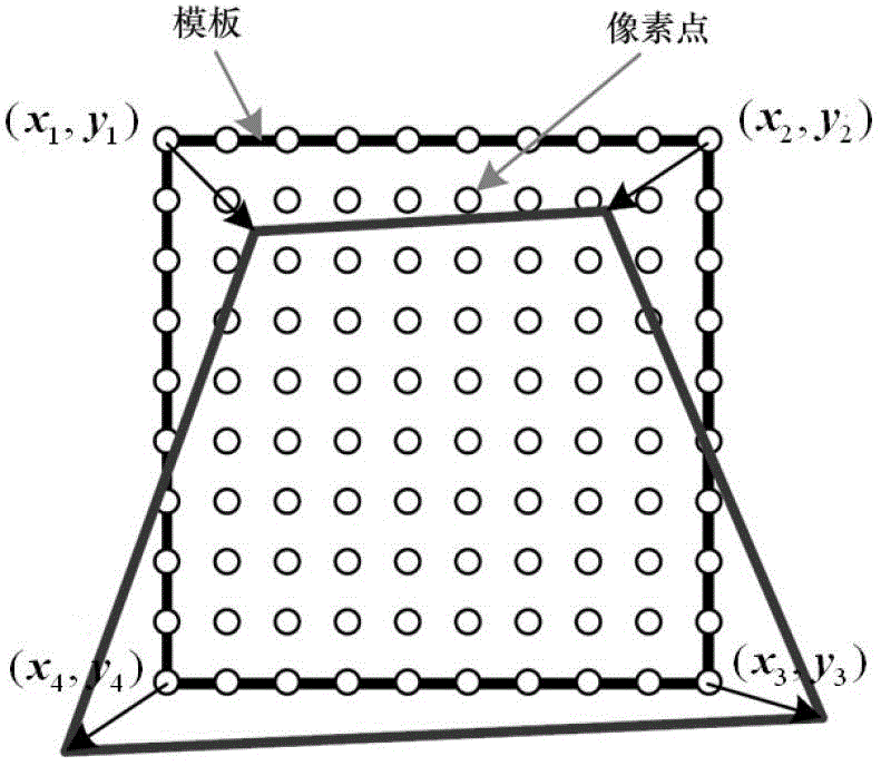
[0058] Step 1. The airborne camera collects the template image of the landing target point and performs affine illumination normalization on the template image to obtain the pixel gray value I of the normalized template image at point x norm (x), where x represents the coordinates of the pixel in the template image;

[0059] For a video sequence, the target motion can be regarded as a three-dimensional motion in two-dimensional space and time dimension. Therefore, the gray value of the pixel point of the real-time input image at x=(x, y) at time t is expressed by I(x , t) said. put a certain t x The real-time video image at the moment is selected as the reference image, and for the target area selected in the reference image, a point set containing N elements can be used represent, and the column vector I(x,t) of the image gray value corresponding to t...


PUM


Abstract

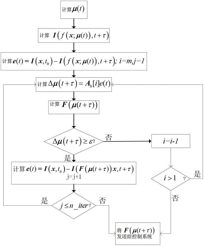
The invention discloses an unmanned aerial vehicle autonomous navigation landing visual target tracking method. The method comprises the steps that: firstly, movement amplitude of a target between two consecutive frame images is divided into a plurality of resolution levels according to an order of 'coarse-to-fine'; prior movement simulation of different levels through an off-line training mode and calculation of corresponding prior error Jacobian matrixes are carried out; and as computing of each level of Jacobian matrix is combined with prior knowledge of training, an algorithm in an iterative search target process can be guaranteed to skip from a local optimum effectively to avoid tracking failure. The target is described by using sparse features of a template image target area, namely a gray value of a FAST corner point portion. Compared with a traditional Lucas-Kanade algorithm, complexity of the algorithm provided by the invention is reduced greatly, wherein dense expression targets of all pixels of the target area are often used in the traditional algorithm.

Description

technical field [0001] The invention relates to an inverse compound target tracking method based on multi-resolution motion prior, which is especially suitable for the stable tracking of targets in the process of visual autonomous guidance and landing of unmanned aerial vehicles, and belongs to the field of digital image processing. Background technique [0002] Visual autonomous landing of UAV is a hot issue in the research field of UAV control. It uses digital image processing technology to obtain positioning parameters, and has many advantages such as simple equipment, low cost, and large amount of information obtained. Compared with GPS and inertial navigation, it is completely autonomous and passive. The rapid and stable matching and tracking of the scheduled landing site template image and the airborne real-time image are the prerequisites for precise landing control. During the landing process of the UAV, the target matching image often has rotation, scale and viewi...

Claims


Application Information

Patent Timeline
Patent Type & Authority Patents(China)
IPC IPC(8): G06K9/00G06K9/60
Inventor 郑智辉汪渤高志峰周志强董明杰石永生沈军李笋王海螺
Owner BEIJING INSTITUTE OF TECHNOLOGYGY
Learn More