Facility controlling system and method

A technology for facility management and management zoning, applied in heating and ventilation control systems, heating and ventilation safety systems, heating methods, etc., can solve problems such as inability to save power and achieve the effect of reducing operating efficiency

Inactive Publication Date: 2012-10-17
YAMATAKE HONEYWELL CO LTD
View PDF7 Cites 9 Cited by
  • Summary
  • Abstract
  • Description
  • Claims
  • Application Information

AI Technical Summary

Problems solved by technology

As a result, there is a problem that the air-conditioning equipment in an arbitrary area cannot perform detailed power-saving operation in accordance with the number of people existing in the area.

Method used


Image

  • Facility controlling system and method
  • Facility controlling system and method
  • Facility controlling system and method

Examples


no. 1 approach

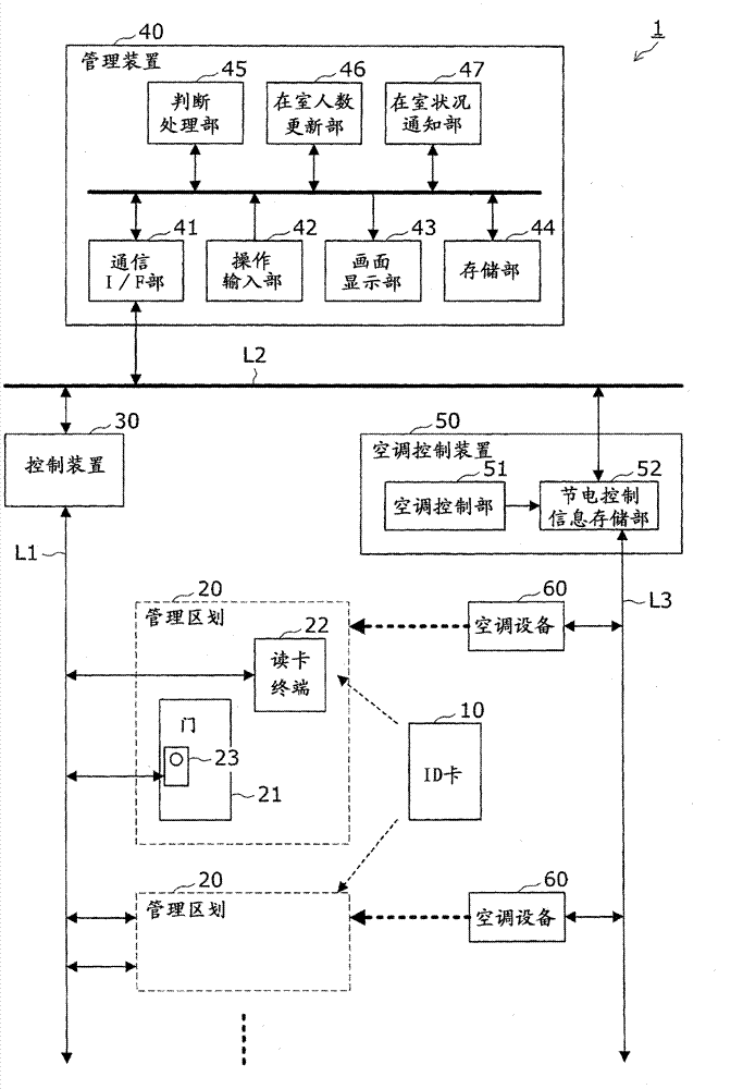
[0036] First, refer to figure 1 The facility management system 1 according to the first embodiment of the present invention will be described. figure 1 It is a block diagram showing the configuration of the facility management system according to the first embodiment.

[0037] This facility management system 1 has the following functions: the management device 40 manages the entry and exit of people for each management area 20 installed in the facility, and performs air-conditioning control in each management area 20 in conjunction with the air-conditioning control device 50 . , Perform power-saving operation here.

[0038] The facility management system 1 includes: an ID card 10 , a card reader terminal 22 , an electronic lock 23 , a control device 30 , a management device 40 , an air conditioner control device 50 and an air conditioner 60 .

[0039]The card reader terminal 22 and the electronic lock 23 provided for the door 21 of each management area 20 are respectively co...

no. 2 approach

[0099] Next, the facility management system 1 according to the second embodiment of the present invention will be described.

[0100] In the first embodiment, a case in which the management division, which is the management unit for entering and leaving a room, and the air-conditioning division, which is the control unit for air-conditioning control, correspond to each other on a 1-to-1 basis has been described as an example. In this embodiment, a case where these management divisions and air-conditioning divisions do not correspond to each other on a one-to-one basis will be described.

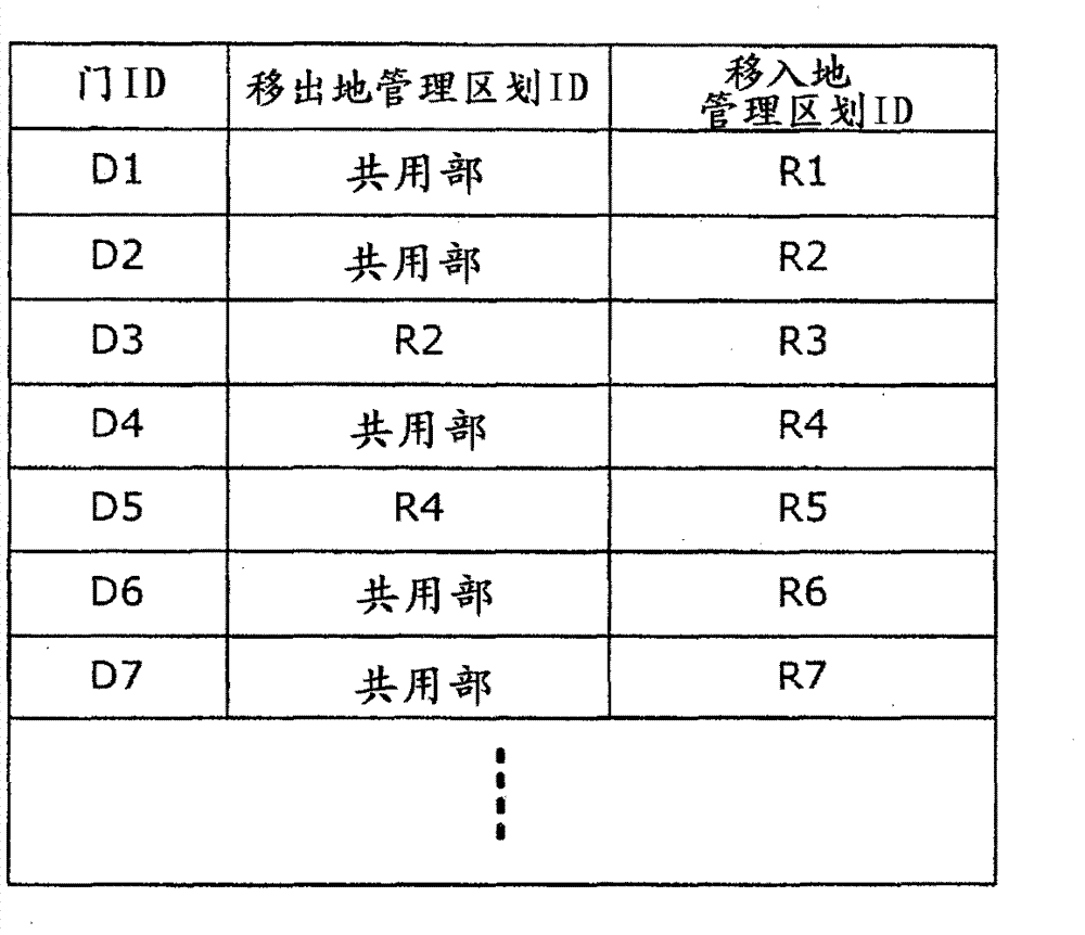
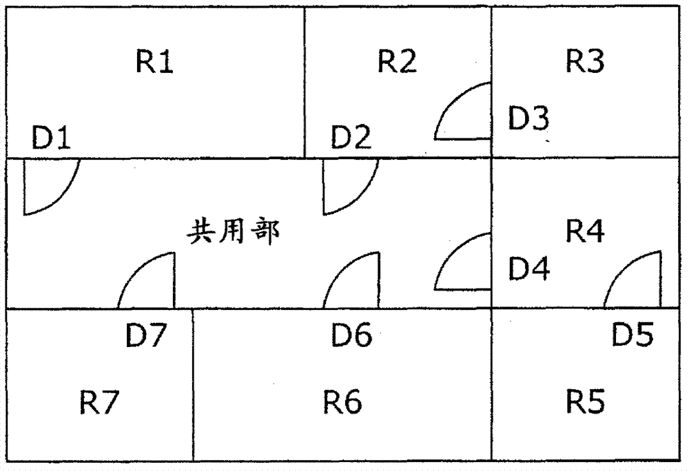
[0101] Figure 11 It is other configuration examples of division. Here, with image 3 Similarly, seven management divisions R1-R7 are arranged so as to surround the shared part. In this embodiment, among these management regions R1-R7, the management regions R1-R3 are used as an air-conditioning region K1 to perform air-conditioning control through the same air-conditioning equipment 60, a...


PUM


Abstract

The invention relates to a facility controlling system and a method, which carry out optimal electricity-saving operation according to the occupant counts in regions. When, in an administering device (40), there has been an evaluation that a user is authorized to enter into any given controlled region, the occupant counts of a movement origin controlled region and of a movement destination controlled region are updated by an occupant count updating portion and stored in a storing portion, in a status noticing portion (47) the occupancy statuses specified by the individual occupant counts in the storing portion are reported to an air-conditioning controlling device (50). In the air-conditioning controlling device (50), electricity-saving control parameters corresponding to the applicable occupancy statuses are obtained from an electricity-saving control information storing portion (52) by an air-conditioning controlling portion (51) in response to occupancy statuses reported by the administering device (40), to cause air-conditioning equipment, corresponding to the applicable region, to perform electricity-saving operation based on the electricity-saving control parameters.

Description

technical field [0001] The present invention relates to facility management technology, and particularly to facility management technology for performing air-conditioning control according to the number of people present in a target area. Background technique [0002] Conventionally, there has been proposed a technique of air-conditioning control in conjunction with the entry / exit of people managed by the entry-exit management device (for example, refer to Patent Document 1, etc.). In this technology, the air conditioner control panel is connected to the interlocking card reader, and a mechanism for selecting the circuit of the air conditioner on / off control is set on the interlocking card reader, and the air conditioner is controlled by the air conditioner control panel by operating the mechanism. On / off control. According to this structure, when entering / exiting the hall, the electronic lock is unlocked in the interlocking card reader, and the air conditioner of the line ...

Claims


Application Information

Patent Timeline
IPC IPC(8): G07C9/00
CPCF24F2011/0075F24F11/0034F24F11/30F24F2120/10F24F11/46F24F11/64F24F11/62F24F2140/60
Inventor 小林弘明
Owner YAMATAKE HONEYWELL CO LTD
Why Eureka
Try Eureka