
Display panel, display and electronic device

A display panel and panel technology, applied to static indicators, instruments, electrical components, etc., can solve problems such as inability to separate colors

Inactive Publication Date: 2012-10-24
JAPAN DISPLAY INC
View PDF5 Cites 11 Cited by
  • Summary
  • Abstract
  • Description
  • Claims
  • Application Information

AI Technical Summary

Problems solved by technology

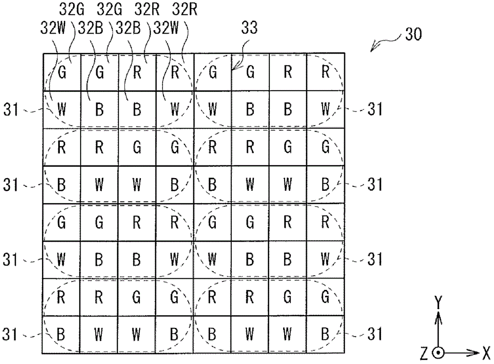
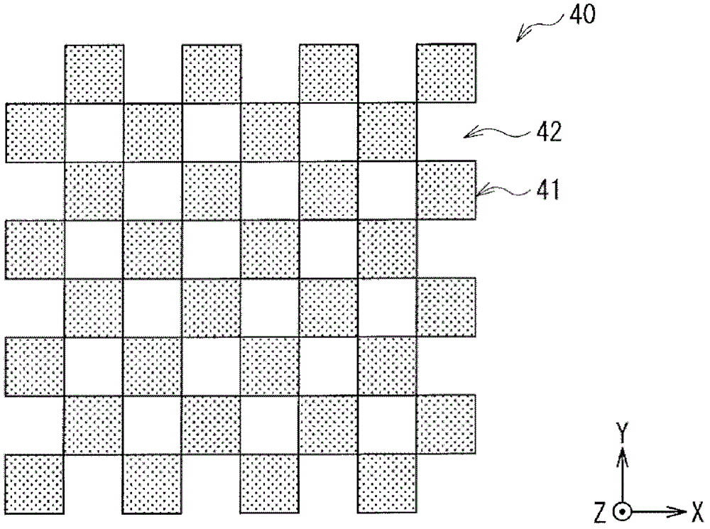
However, in the case of using a known grating pattern having a checkered pattern (that is, in the pattern in which light-shielding regions and light-transmitting regions are alternately arranged in the row and column directions) as the grating layer, there is There is a problem that some of the four colors are masked by the raster pattern, and therefore color separation of perspective cannot be performed

Method used


Image

  • Display panel, display and electronic device
  • Display panel, display and electronic device
  • Display panel, display and electronic device

Examples


Embodiment approach

[0036] structure

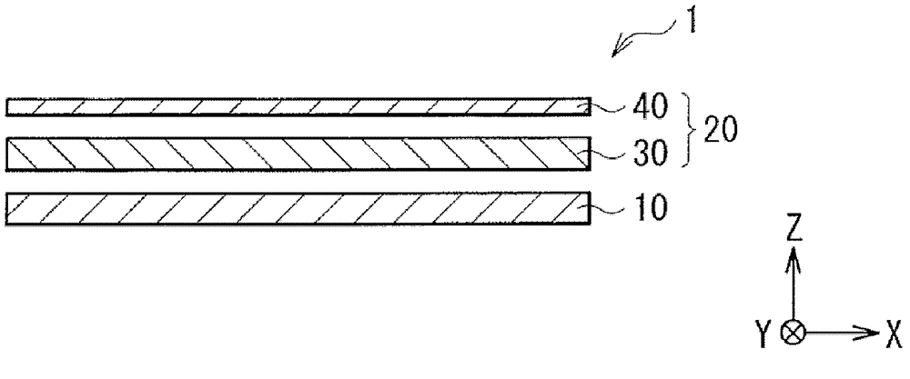
[0037] figure 1 An exemplary cross-sectional structure of the display 1 of the embodiment is shown. have to be aware of is, figure 1 It is only a schematic diagram, and the actual size and shape may not be the same. The display 1 includes a display panel 20 , a backlight 10 arranged on the back of the display panel 20 , and a driving circuit (not shown) for driving the display panel 20 . The backlight 10 is a surface emitting light source that illuminates the display panel 20 from the back. The upper surface of the display panel 20 is an image display surface. The display panel 20 has a panel portion 30 and a grating portion 40 .

[0038] figure 2 express figure 1 An exemplary planar structure of the panel portion 30. image 3 express figure 1 An exemplary planar structure of the grating portion 40.

[0039] The panel section 30 is a transmissive panel in which each pixel 31 is driven based on an image signal input from the outside. The panel uni...


PUM


Abstract

A display panel includes: a panel section including a plurality of pixels disposed in a row direction and a column direction,and a barrier section including light blocking regions and light transmitting regions alternately disposed in the row direction and the column direction, wherein each of the pixels emits light of four colors, and has two sub-pixels for each of the four colors. According to the invention, the color separation can be realized under the condition of each of pixels provided with four color structures.

Description

[0001] Cross References to Related Applications [0002] This application contains subject matter related to that disclosed in Japanese Priority Patent Application JP 2011-091845 filed in the Japan Patent Office on Apr. 18, 2011, the entire content of which is hereby incorporated by reference. technical field [0003] The present invention relates to a display panel capable of multi-view display that allows different two-dimensional images (planar images) to be visually recognized from each viewpoint, and a display including the same A specific viewpoint visually recognizes a three-dimensional display of a three-dimensional image (stereoscopic image). In addition, the present invention relates to electronic equipment including the above-mentioned display. Background technique [0004] In recent years, displays capable of multi-view display or three-dimensional display have been put into practical use. For example, a display panel provided with a grating layer on its displa...

Claims


Application Information

Patent Timeline
Patent Type & Authority Applications(China)
IPC IPC(8): G02B27/22H04N13/04G09G3/20G02B30/30
CPCH04N13/0409G02B27/2214G09G2300/0443G09G2300/0452G09G3/32G09G3/28H04N13/31G02B30/30G02B30/27
Inventor 上原利范金子英树池田幸次朗铃木大地
Owner JAPAN DISPLAY INC
Learn More