Substrate conveying apparatus and method

A technology of conveying device and substrate, applied in the direction of conveyor, conveyor objects, transportation and packaging, etc., can solve problems such as interference between worktable and guide rail, inability to install multiple electronic components, and wrong assembly.

Active Publication Date: 2012-10-31
SHIBAURA MECHATRONICS CORP
View PDF4 Cites 11 Cited by
  • Summary
  • Abstract
  • Description
  • Claims
  • Application Information

AI Technical Summary

Problems solved by technology

[0014] However, when the interval adjustment of the pair of guide rails and the positioning adjustment of the table relative to the pair of guide rails are performed, work mistakes may occur, or a table of the wrong size may be assembled.
[0015] If the above-mentioned table is mistaken for a table larger than the size to be replaced, the table and the guide rail will interfere, and if the table is mistaken for a small table on the contrary, the end of the width direction of the table will The distanc...

Method used


Image

  • Substrate conveying apparatus and method
  • Substrate conveying apparatus and method
  • Substrate conveying apparatus and method

Examples


Embodiment Construction

[0045] Embodiments of the present invention will be described below with reference to the drawings.

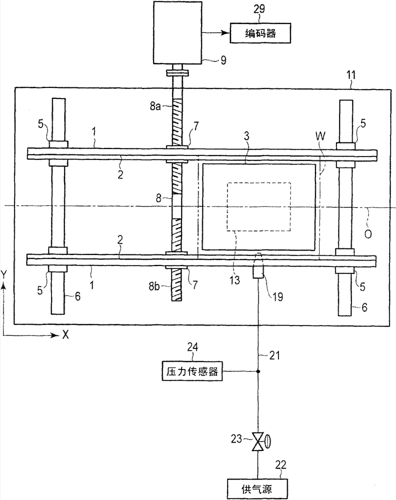
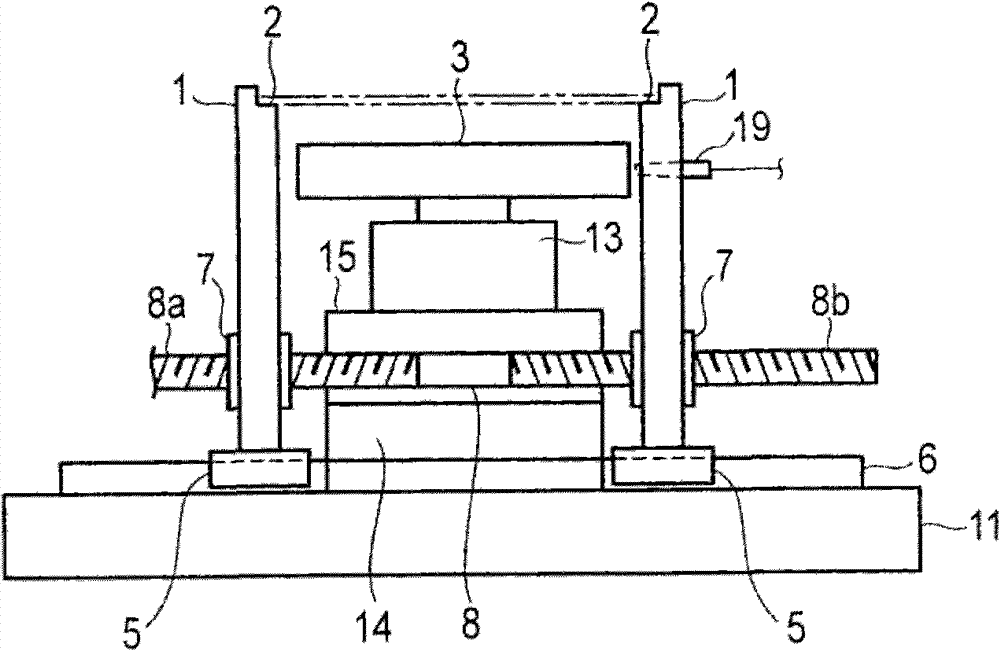
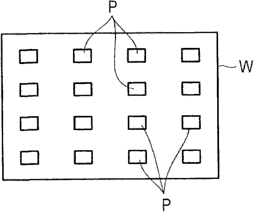
[0046] Figure 1-Figure 6 The first embodiment of the present invention is shown. figure 1 The conveying device shown has a rectangular base plate 11 . A pair of guide rails 1 spaced apart at a predetermined interval are provided in the width direction of the upper surface of the substrate 11 . Let the departure direction of a pair of guide rails 1 be figure 1 The Y direction in the X and Y directions shown. At the upper end of a pair of guide rails 1, such as figure 2 As shown, there are formed step portions 2 on which both end portions in the width direction of the substrate W on which electronic components P such as IC chips are mounted are engaged and supported.

[0047] The substrate W placed on both ends in the width direction engaged with the step portion 2 is conveyed at intervals of a predetermined distance along the guide rail 1 by a chuck mechanism (not shown)...


PUM


Abstract

The invention provides a substrate conveying apparatus and method. The substrate conveying apparatus comprises the following components: a spaced rotary drive source (9) provided with a pair of guide rails (1), a workbench (3) supporting the lower portion of the substrate at two end portions in the width direction supported by the pair of guide rails, a nozzle body (19) that makes the positive/negative air pressure work on the end face in the width direction of the workbench between the guide rails, a pressure sensor (24) used for detecting the pressure changes of the gas resulting from the interval change of the nozzle body and the side face of the workbench by making the air pressure work on the side face of the replaced workbench and driving the guide rails equipped with the nozzle body in the direction approaching the side face of the workbench, when the substrate size is changed and the workbench is changed into a workbench having different width size, and a control apparatus used for detecting the pressure changes of the gas flowing through the nozzle body via a pressure sensor, controlling the driving of a rotary drive source, and setting the space for a pair of guide rails.

Description

technical field [0001] The invention relates to a substrate conveying device and a conveying method for conveying and positioning a substrate along a pair of guide rails. Background technique [0002] For example, when electronic components such as IC chips are mounted on a substrate, the substrate is conveyed along guide rails to a mounting position where a mounting stage is provided, and if the lower surface of the substrate is supported by the stage at the mounting position , the above-mentioned electronic component is mounted on the upper surface of the above-mentioned substrate by using a mounting tool. [0003] The substrate is supported at both ends in the width direction by a pair of guide rails parallel to each other, and is intermittently conveyed at predetermined distances along the guide rails by, for example, a transfer mechanism such as a chuck mechanism. [0004] When mounting the above-mentioned electronic components on the above-mentioned substrate, the mou...

Claims


Application Information

Patent Timeline
IPC IPC(8): H01L21/677
CPCB65G47/911B65G49/065B65G2249/045H01L21/67784H05K13/021
Inventor 佐藤裕一上原贞人
Owner SHIBAURA MECHATRONICS CORP
Why Eureka
Try Eureka