Cutting machine

A cutting machine and workbench technology, which is applied to metal sawing equipment, sawing machine devices, metal processing equipment, etc., can solve the problems of difficulty in replacing saw blades and inconvenience for users, and achieve the effect of simple and convenient replacement process

Active Publication Date: 2012-11-14
POSITEC POWER TOOLS (SUZHOU) CO LTD
View PDF6 Cites 1 Cited by
  • Summary
  • Abstract
  • Description
  • Claims
  • Application Information

AI Technical Summary

Problems solved by technology

[0004] However, during use, users often need to replace different types of saw blades for different working conditions.

Method used


Image

  • Cutting machine
  • Cutting machine
  • Cutting machine

Examples


Embodiment Construction

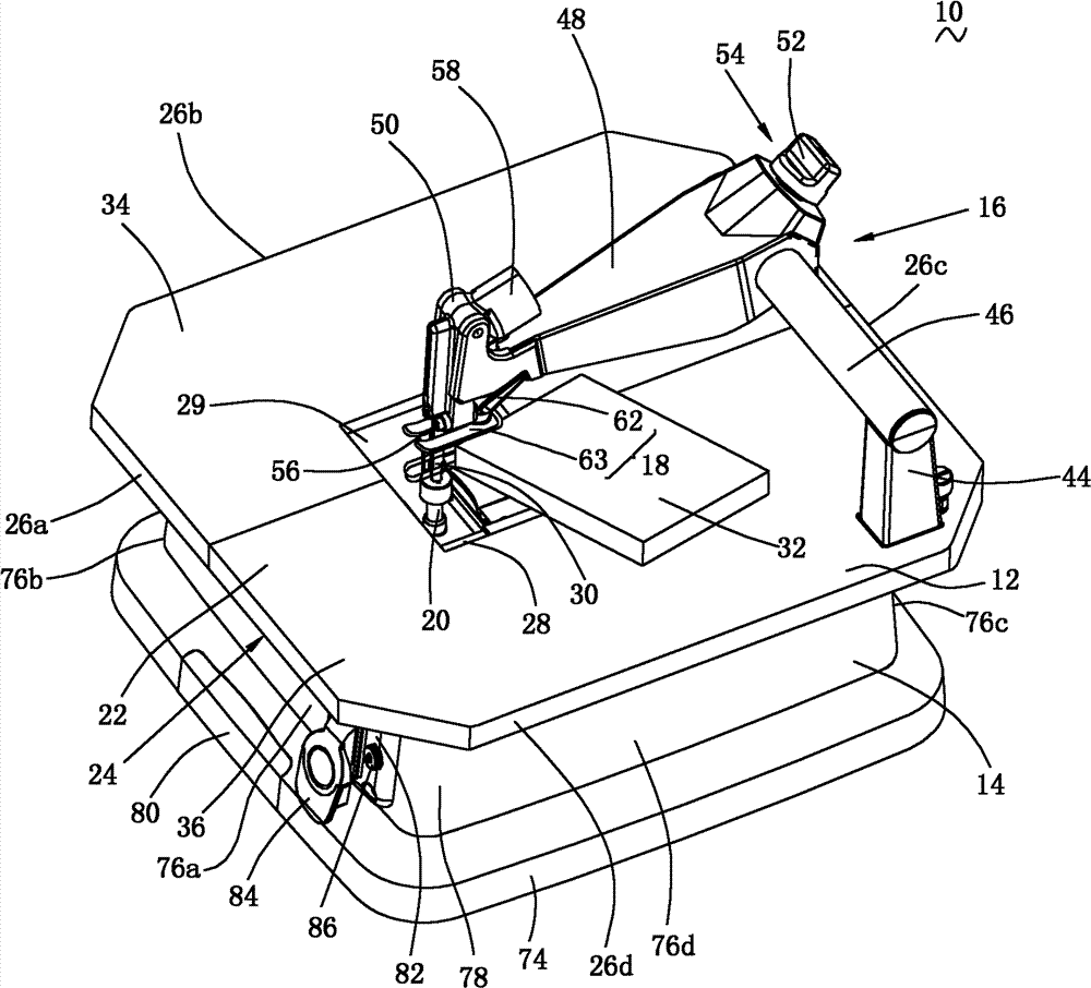
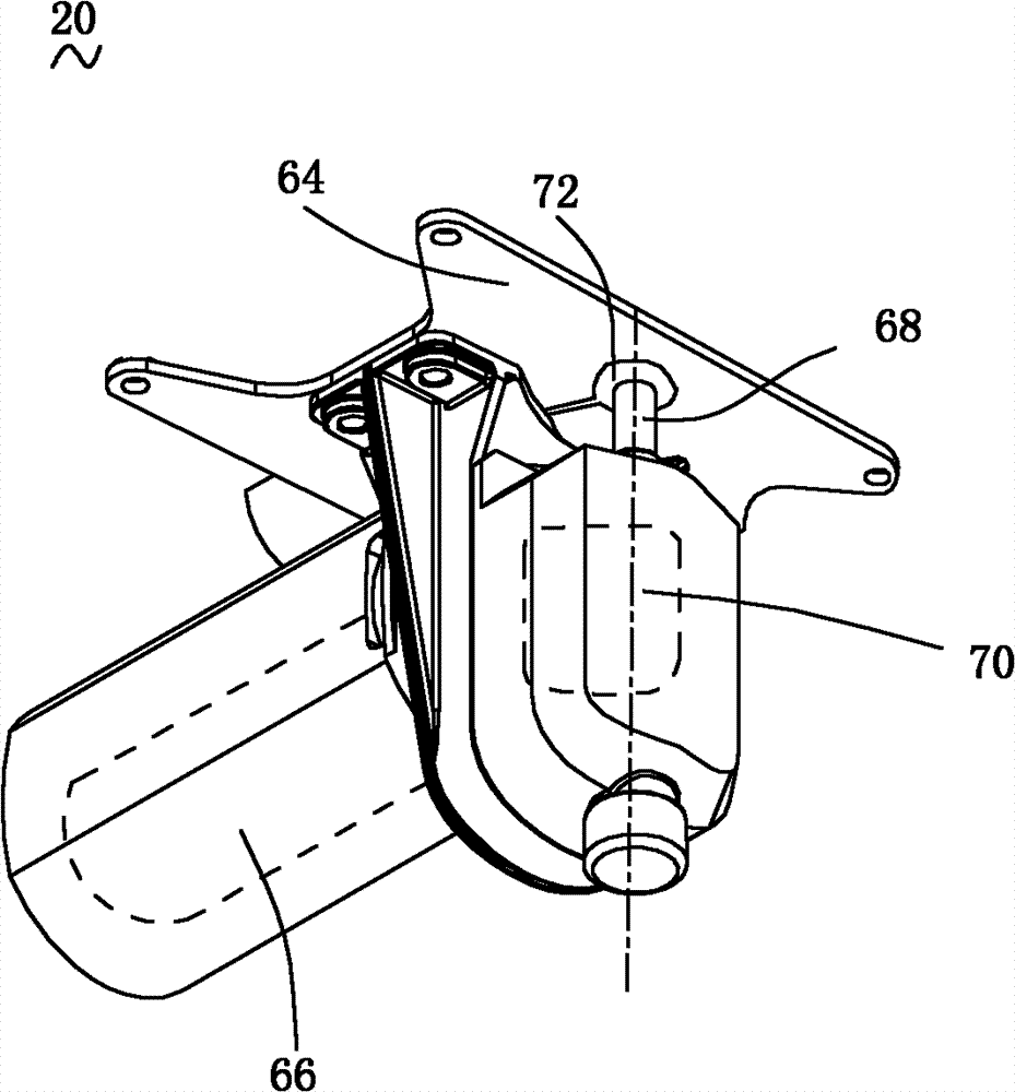
[0049] see figure 1 , a cutting machine 10 provided in the first embodiment of the present invention, including a workbench 12, a support 14 supporting the workbench 12, a shield assembly 16 arranged on the workbench 12, connected with the shield assembly 16 and adjustable The pressing plate assembly 18 that exerts a certain pressure on the workpiece 32 , and the cutting mechanism 20 accommodated in the support 14 .

[0050] According to the user's usual way of using this type of cutting machine, define figure 1 The middle left is the front part of the cutting machine 10, and the right side is the rear part of the cutting machine 10.

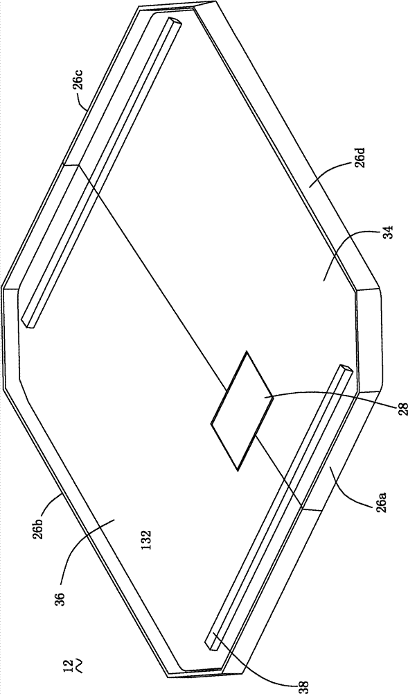
[0051] Please also refer to figure 1 and figure 2 , the workbench 12 has a workpiece supporting surface 22 capable of supporting the workpiece 32, a mounting surface 24 facing away from the workpiece supporting surface 22 and mated with the support 14, and a side wall 26a extending vertically relative to the workpiece supporting surface 22 a...


PUM


Abstract

The invention relates to a cutting machine, comprising a worktable, a support and a cutting mechanism, wherein the worktable is provided with an opening and comprises a workpiece supporting surface for supporting workpieces and a mounting surface back to the workpiece supporting surface; the support supports the worktable; the cutting mechanism is located in a space encircled by the mounting surface of the worktable and the support, and comprises a motor for outputting rotary movement, a reciprocating lever for driving a saw which passes through the opening to move to and fro, a movement switching mechanism for switching the rotary drive of the motor into the reciprocating movement of the reciprocating lever, and a saw clamping and releasing mechanism for operably clamping and releasing the saw; at least part of the worktable is capable of moving relative to the support, so that the saw clamping and releasing mechanism can be touched. Compared with the prior art, by adopting the cutting machine, the saw replacing process is simple and convenient, and time and labour are saved.

Description

technical field [0001] The invention relates to a cutting machine, in particular to a cutting machine with a reciprocating cutting mechanism. Background technique [0002] Existing jigsaws can perform various curved and straight cuts, and are therefore widely used in processing boards of various materials. Generally, a jigsaw includes a motor, a housing housing the motor, a motion conversion mechanism housed in the gear box housing, driven by the motor and converting the rotational motion of the motor into the reciprocating motion of the reciprocating rod, and connected to the reciprocating rod through a chuck device The saw blade, and the bottom plate that supports the body of the jigsaw on the surface of the workpiece. [0003] In order to expand the application of the jigsaw, technicians in the industry place it upside down on the lower surface of a workbench, so that the cutting process can be performed when the workpiece needs to be moved. In order to better support t...

Claims


Application Information

Patent Timeline
IPC IPC(8): B23D51/02B23D51/08
Inventor 何明明
Owner POSITEC POWER TOOLS (SUZHOU) CO LTD
Why Eureka
Try Eureka