
Push and twist electrical connector assembly

a technology of electrical connectors and assembly parts, applied in the direction of coupling device connections, coupling parts engagement/disengagement, electrical apparatus, etc., can solve the problems of changing including the housing and stem, and the replacement of the entire light fixture, so as to achieve the effect of convenient and convenient replacement of only the socket and bulb portions

Inactive Publication Date: 2006-12-26
LOWEL LIGHT MFG
View PDF20 Cites 7 Cited by
  • Summary
  • Abstract
  • Description
  • Claims
  • Application Information

AI Technical Summary

Benefits of technology

"The present invention provides an apparatus for easily and conveniently replacing only the socket and bulb portions of a light fixture without having to replace the entire light fixture. This is achieved through a push and twist electrical connector assembly that includes a base assembly and a latch assembly. The latch assembly includes a male pin contact holder and a female pin contact holder with tabs for mating connection with the electrical female connector. The latch assembly can be connected to the base assembly by inserting the male pin contacts into the female pin contacts and rotating or twisting the base assembly with respect to the latch assembly. The latch assembly can receive different types of platform assemblies for different light sources, and the compatibility of the light fixture with the light source is dictated by the number of protruding security screws in the base assembly. The invention provides a convenient and flexible solution for replacing light fixture parts without having to replace the entire light fixture."

Problems solved by technology

As a result, when it is desired to change the type of lamp bulb used, it is necessary to change the entire light fixture because the socket of one type of lamp bulb will typically not accommodate other lamp bulb types.
However, the light fixture is limited to only a certain type of bulb or bulbs that will be accommodated by the specific type of socket that is contained within the housing.
For using different types of lights with the reflector described above, the entire light fixture, including the housing and stem, has to be replaced which is cumbersome and inefficient.
Although a variety of electrical connectors are known in the art as described below, none of these electrical connectors are designed for lighting fixtures or satisfy the problem identified above.

Method used


Image

  • Push and twist electrical connector assembly
  • Push and twist electrical connector assembly
  • Push and twist electrical connector assembly

Examples


Embodiment Construction

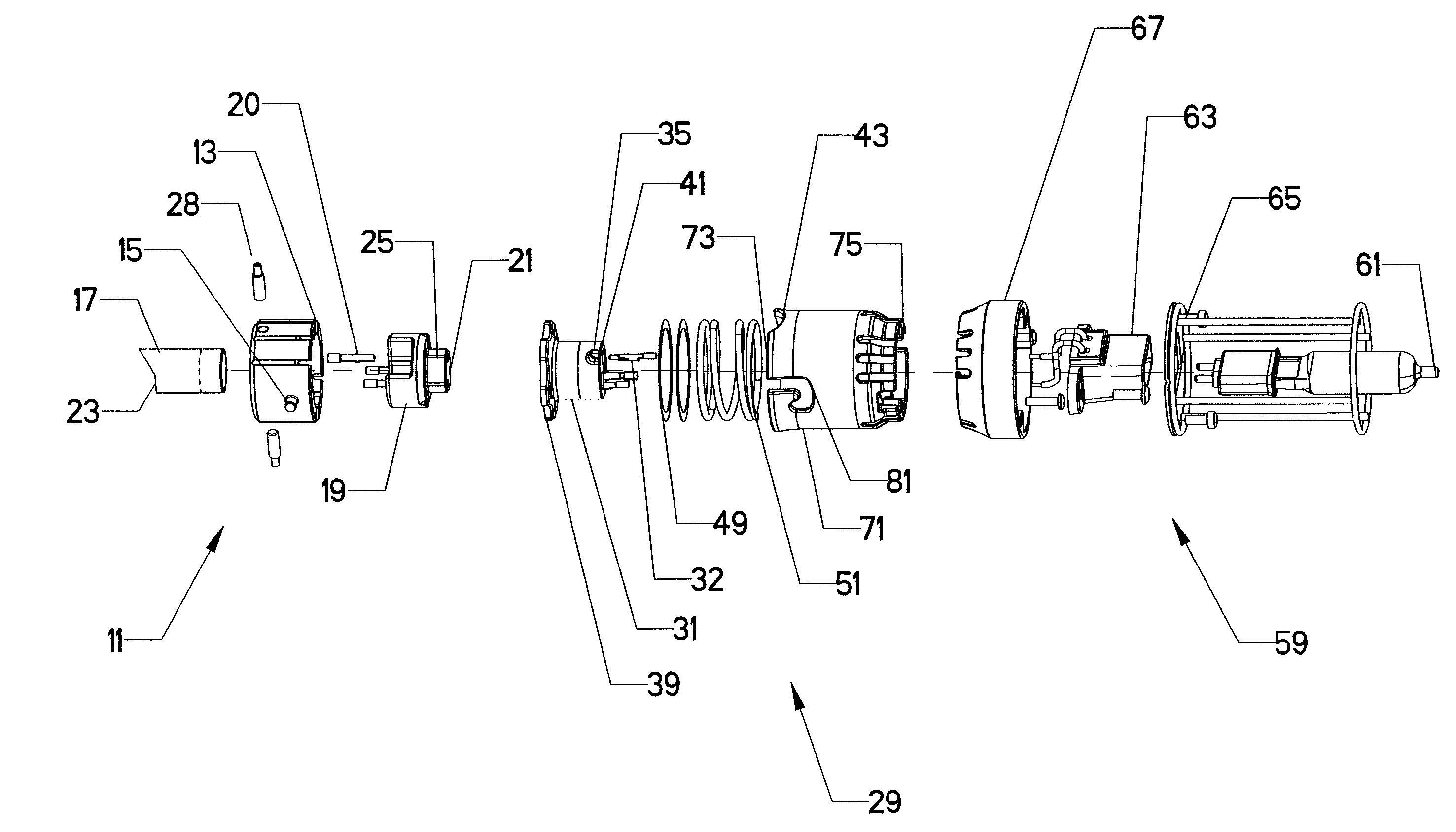
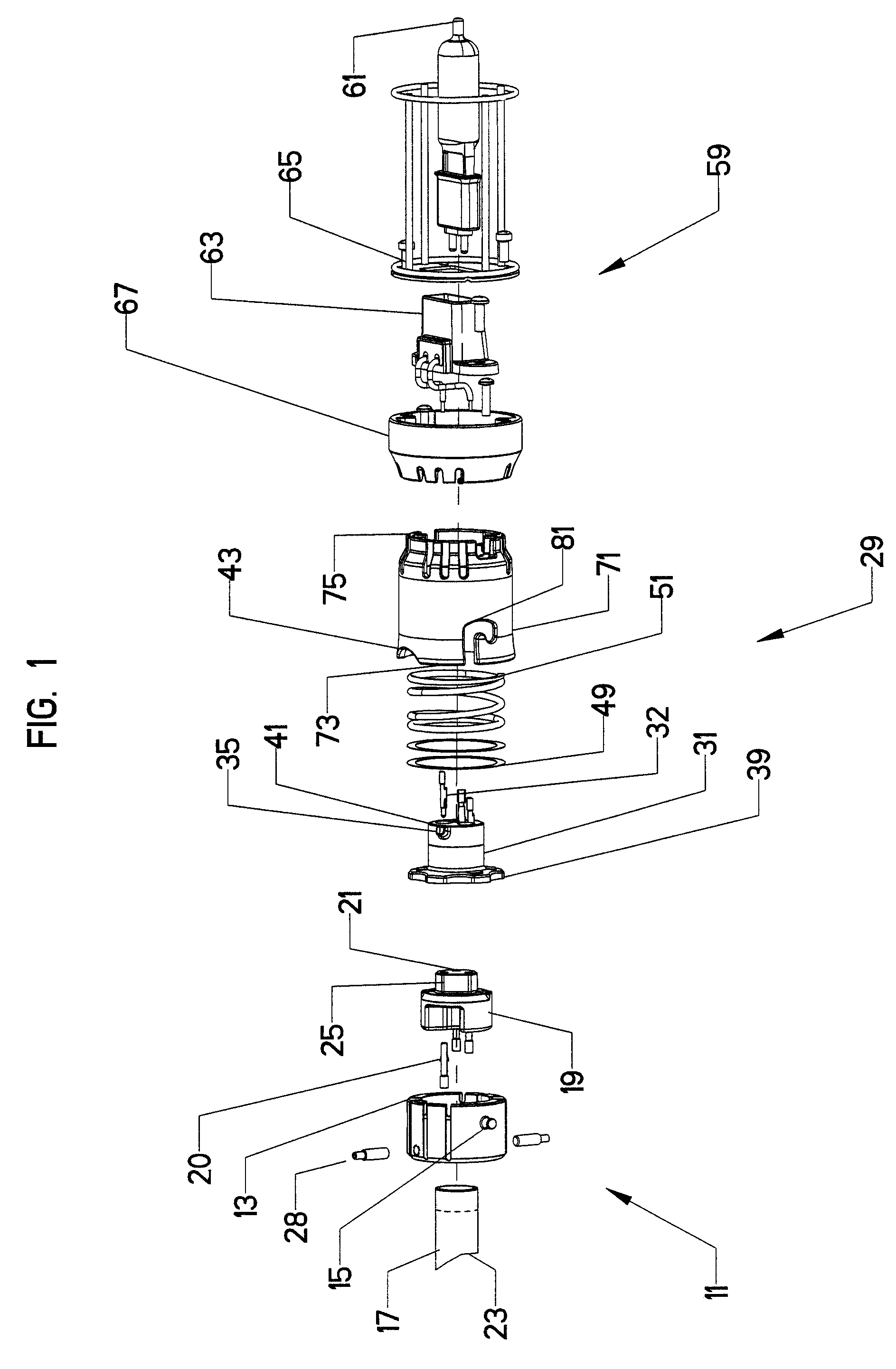
[0038]Referring now to the drawings, in which like reference numerals are used to refer to the same or similar elements, FIG. 1 shows the components of a base assembly 11, a latch assembly 29, and an example of a platform assembly 59 for a light fixture or electrical device of the present invention.

[0039]The base assembly 11 includes a female pin contact holder 19 containing female pin contacts 20 and a male protrusion 25 at a first end 21 of the base assembly 11, a base housing 13 adjacent the female pin contact holder 19 and having diametrically opposed guide posts 15 which are cylindrical, and a stem 17 extending from the base housing to a second end 23 which is opposite the first end 21. The female pin contact holder has a male protrusion 25 for mating the female pin contact holder 19 to a male pin contact holder 31. The female contacts are examples of first contacts of the invention that are part of the base assembly.

[0040]Although the guide posts 15 are preferably cylindrical,...


PUM


Abstract

An electrical device has a base assembly including first contacts and a mounting mechanism for electrically leading to a power source, a latch assembly adapted to receive at least one additional electrical device that is to be mounted to the latch assembly, push and twist mechanism for engaging the latch assembly to the base assembly and a plurality of second contacts in the latch assembly adapted to be electrically connected to the first contacts of the base assembly, the second contacts being adapted to be connected to the additional electrical device.

Description

CROSS-REFERENCE TO RELATED APPLICATION[0001]This is a continuation of application Ser. No. 11 / 353,782 filed Feb. 14, 2006, which is incorporated here by reference and is now U.S. Pat. No. 7,081,001 issued Jul. 25, 2006.FIELD AND BACKGROUND OF THE INVENTION[0002]The present invention relates generally to the field of electrical connectors and in particular to a new and useful electrical connector assembly for light fixtures.[0003]There are many different types of light fixtures which have different types of sockets and different types of bulbs, such as incandescent lamp bulbs, fluorescent lamp bulbs, halogen lamp bulbs, and high intensity discharge (HID) lamp bulbs. As a result, when it is desired to change the type of lamp bulb used, it is necessary to change the entire light fixture because the socket of one type of lamp bulb will typically not accommodate other lamp bulb types.[0004]Although the above-mentioned problem exists in environmental lighting in general, one example of th...

Claims


Application Information

Patent Timeline
Patent Type & Authority Patents(United States)
IPC IPC(8): H01R13/62
CPCH01R13/625H01R33/90H01R33/06
Inventor CONROY, DAVIDYU, CHI
Owner LOWEL LIGHT MFG
Learn More