Eureka AIR delivers breakthrough ideas for toughest innovation challenges, trusted by R&D personnel around the world.

Induction cooker with novel radiating structure

A heat dissipation structure and technology of induction cooker, applied in the field of induction cooker, can solve problems such as lack of heat dissipation space, electrical failure of the cooker, influence on lifespan, etc., and achieve the effect of compact structure, convenient maintenance and elimination of machinery

Active Publication Date: 2014-11-05
MIJI ELECTRONICS & APPLIANCES SHANGHAI
View PDF4 Cites 0 Cited by
  • Summary
  • Abstract
  • Description
  • Claims
  • Application Information

AI Technical Summary

Problems solved by technology

[0003] see Figure 7 The disadvantages of the above cooling methods are: 1. The induction cooker shell must have cooling air slots 1-3. The existence of these cooling air slots must consider the waterproof and anti-insect penetration design, otherwise the stove will often be caused by overflowing pots and insects. Electrical failure; 2. The fan 1-2 is used to dissipate heat on the PCB board 1-4, and the moving parts of the fan 1-2--the motor and the impeller will generate noise and wear, and the service life will also be affected; 3. The original stacked heat sink 1-1 is fixed on the PCB board next to the fan 1-2, and the heating element is fixed on the back of the stacked heat sink 1-1, so that the components inside the induction cooker are concentrated on one PCB board , relatively congested, relatively lack of heat dissipation space

Method used


Image

  • Induction cooker with novel radiating structure
  • Induction cooker with novel radiating structure
  • Induction cooker with novel radiating structure

Examples


Embodiment 1

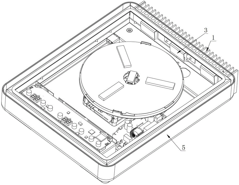
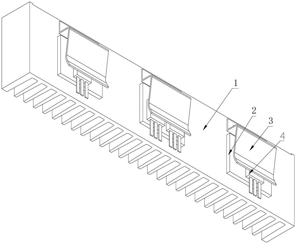
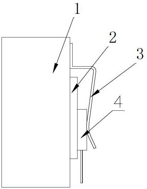
[0024] See Figure 1 ~ Figure 4 and Image 6 In the present invention, a heat sink 1 is provided on one side of the furnace body 5 of the induction cooker, the hot end surface of the semiconductor heat sink 2 is attached to the inner side of the heat sink 1, and the heating element 4 is fixed on the cold end surface of the semiconductor heat sink 2 by using a fixed spring 3 On; the fixed portion of the fixed elastic sheet 3 is provided on the heat sink 1 above the corresponding semiconductor heat sink 2, and the abutment portion below the fixed elastic sheet 3 is located on the outer side of the heating element 4, thereby clamping the heating element 4 in the semiconductor On the heat sink 2, an auxiliary PCB board 7 is additionally provided on the bottom plate of the furnace body below the corresponding heating element 4. Considering that the heating element 4 is mainly the IGBT and the rectifier bridge, other elements do not need to dissipate heat separately because the heat ...


PUM


Abstract

The invention relates to the technical field of induction cookers, in particular to an induction cooker with a novel radiating structure. The induction cooker is characterized in that a radiating plate is arranged on a side surface of a cooker body; heat end surfaces of semiconductor radiating fins are adhered to an inner side surface of the radiating plate on the cooker body; heating elements are fixed on cold end surfaces of the semiconductor radiating fins by fixing spring plates; fixing parts of the fixing spring plates are arranged on the inner side surface, which is opposite to the upper sides of the semiconductor radiating fins, of the radiating plate; pressing parts on the lower sides of the fixing spring plates are pressed against the outer side surfaces of the heating elements; and at least one semiconductor radiating fin is arranged on the radiating plate. Compared with the prior art, the induction cooker is light and small in size, mechanical noises and airflow noises are eliminated, the induction cooker is totally closed, a waterproof and mothproof design is not required, and the structure of the induction cooker is compact. In addition, the service life of a semiconductor refrigerating element is far longer than that of a cooling system using a fan with a motor, and cost is reduced effectively.

Description

Technical field [0001] The invention relates to the technical field of induction cookers, in particular to an induction cooker with a novel heat dissipation structure. Background technique [0002] At present, the heat dissipation of the induction cooker is forced air cooling, that is, the small electric fan takes the cooling air from the air inlet through the internal air duct of the induction cooker to take away the heat of the high-power heating elements such as IGBT, rectifier bridge and the additional installed heat sink in the induction cooker. , The induction cooker is discharged through the air outlet slot to keep the temperature of the power element below the temperature that can work safely. [0003] See Figure 7 The disadvantages of the above-mentioned cooling methods are: 1. The induction cooker shell must have cooling air slots 1-3. The existence of these cooling air channels must consider the design of waterproof and anti-insect penetration, otherwise the stove will o...

Claims


Application Information

Patent Timeline
Patent Type & Authority Patents(China)
IPC IPC(8): F24C7/00F24C15/00
Inventor 季残月
Owner MIJI ELECTRONICS & APPLIANCES SHANGHAI
Why Eureka
Eureka Blog
Learn More