Similar test bed and test method for rotor-sliding bearing power
A sliding bearing and dynamic similar technology, applied in the field of radial sliding bearing test devices, can solve the problems of reduced practical significance of the test, large rotors, far different dynamic characteristics, etc., to achieve large engineering reference value, high reference value, and cost saving Effect
Active Publication Date: 2012-12-12
ZHEJIANG UNIV
View PDF0 Cites 19 Cited by
- Summary
- Abstract
- Description
- Claims
- Application Information
AI Technical Summary
Problems solved by technology
[0004] The first type of sliding bearing test bench, the dynamic characteristics of the test rotor and the real rotor are very different, and the shaft is rigid in most cases, which cannot show the nonlinear characteristics and stability of the rotor-bearing system under actual working conditions
There are two problems in the second type of sliding bearing test bench. One is that the static load of the bearing cannot be changed, so it is dif
Method used
View moreImage
Smart ImageViewing Examples
Examples
 PUM
 Abstract
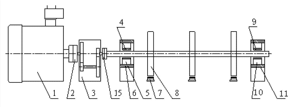
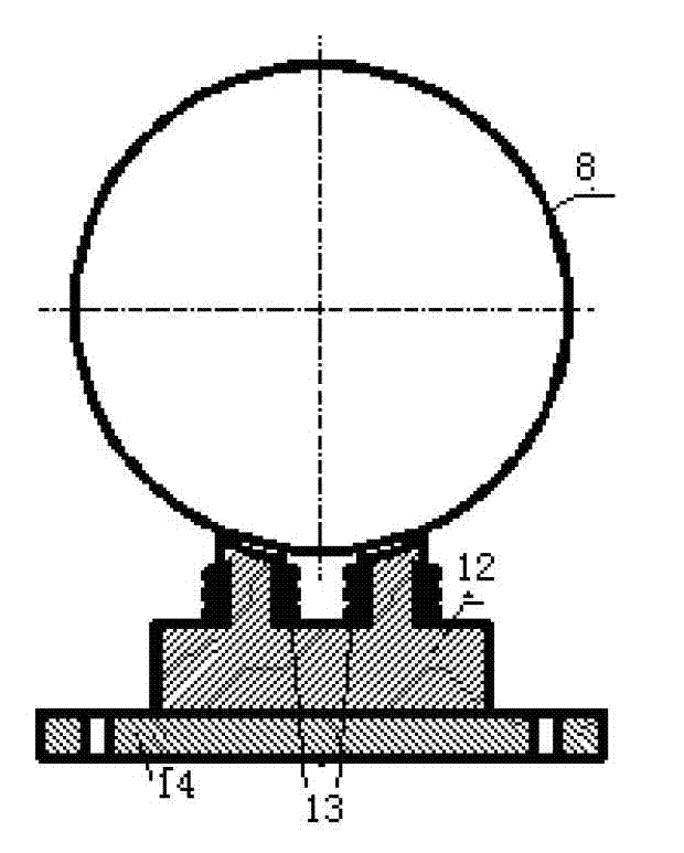
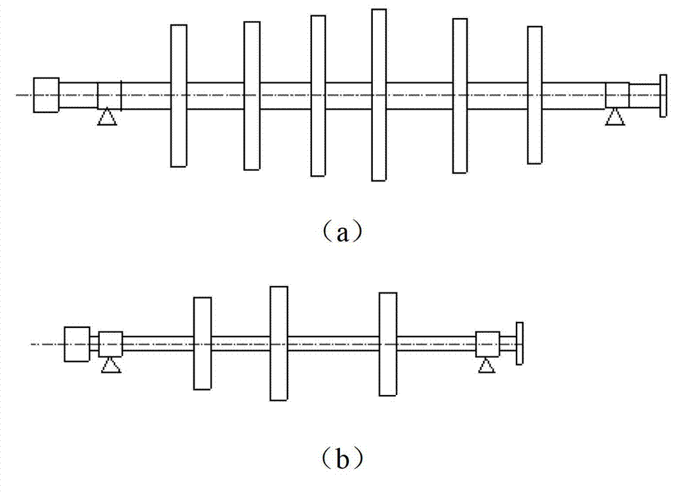
The invention discloses a similar test bed and a test method for a rotor-sliding bearing power, wherein a motor is connected with an overdrive gear box by a first shaft coupling; the overdrive gear box is connected with a rotor by a second shaft coupling; the overdrive gear drives the rotor to rotate; the rotor is supported by a left sliding bearing and a right sliding bearing; the left sliding bearing is connected with a left bearing seat by a left bearing tooling; the right sliding bearing is connected with a right bearing seat by a right bearing tooling; a number of electromagnetic actuators are arranged below the rotor in a non-contact manner; the similar test bed changes a static load of sliding bearings by a non-contact electromagnetic force, reduces an original big rotor into a small test rotor by a power similar principle, and ensures that a test state is uniform to an actual working state for supporting the big rotor; the method is feasible and a test result has a good engineering reference value for a bearing design, ultimate load bearing, a dynamic property analysis and a reliability analysis and the like, thus greatly saving cost.
Description
technical field [0001] The invention relates to the technical field of rotor dynamics, in particular to a radial sliding bearing test device and a test method thereof. Background technique [0002] Hydrodynamic radial sliding bearings are widely used in large-scale high-speed and high-speed precision rotating machinery (such as steam turbines, industrial compressors, nuclear power units and various large machine tools). The damping provided is also the main source of damping in the rotor-bearing system. With the increase in size, speed and capacity of rotating machinery, the stability of the rotor-bearing system is approaching the limit, so the design of the bearing is becoming more and more important. The performance of the sliding bearing directly affects the working accuracy of the entire unit , life, reliability and many other technical and economic indicators. Therefore, in the development of new products or the confirmation of product quality, it is required to examin...
Claims
Login to View More Application Information
Patent Timeline
 IPC IPC(8): G01M13/04
Inventor 郑水英刘淑莲潘晓弘
Owner ZHEJIANG UNIV
Features
- R&D
- Intellectual Property
- Life Sciences
- Materials
- Tech Scout
- Unparalleled Data Quality
- Higher Quality Content
- 60% Fewer Hallucinations
Learn More Browse by: Latest US Patents, China's latest patents, Technical Efficacy Thesaurus, Application Domain, Technology Topic, Popular Technical Reports.
© 2025 PatSnap. All rights reserved.Legal|Privacy policy|Modern Slavery Act Transparency Statement|Sitemap|About US| Contact US: help@patsnap.com


