Eureka AIR delivers breakthrough ideas for toughest innovation challenges, trusted by R&D personnel around the world.

Novel mechanical brake structure

A mechanical brake and brake technology, applied in the field of forging machinery, can solve the problems of inconvenience in installation, maintenance and replacement of parts, and achieve the effect of overcoming installation

Inactive Publication Date: 2012-12-19
梅利
View PDF0 Cites 0 Cited by
  • Summary
  • Abstract
  • Description
  • Claims
  • Application Information

AI Technical Summary

Problems solved by technology

[0003] The purpose of the present invention is to provide a new type of mechanical brake structure, which overcomes the defects of inconvenient installation, maintenance and replacement of parts in the existing brakes.

Method used


Image

  • Novel mechanical brake structure

Examples


Embodiment Construction

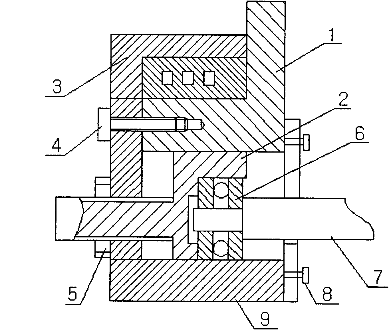
[0008] Fix the sleeve 3 with the brake 1 through the bolt 4, connect the adjustment sleeve 2 with the sleeve 3, install the ejector rod 7 in the blind hole of the adjustment sleeve 2 through the bearing 6, and fix the adjustment sleeve 2 with the brake 1 Together, the locking nut 5 locks the adjusting sleeve 2, and the adjusting plate 9 is installed on the outer circle of the bearing 6 and the ejector rod 7, and the adjusting plate 9 is fixed by the ejector rod bolts.


PUM


Abstract

The invention relates to a novel mechanical brake structure. The structure is characterized in that a sleeve base and a brake are fixed together through a bolt, a regulating sleeve and the sleeve base are connected together, and a push rod is arranged in the blind hole of the regulating sleeve through a bearing; and the regulating sleeve is regulated so as to be fixed together with the brake, the locking nut locks the regulating sleeve, a regulating plate is arranged on the excircle of the bearing and the push rod, and the regulating plate is fixed by a post rod bolt.

Description

technical field [0001] The invention relates to a structure of a mechanical brake, in particular to a structure of a novel mechanical brake. It belongs to the technical field of forging machinery. Background technique [0002] At present, the structure of brake components is composed of brake discs, bearings, lock nuts, ejector rods, etc. Since the bearings are installed in the adjustment sleeve, the end of the adjustment sleeve where the bearing is installed is installed in the brake in a closed state. Once the bearing If it is damaged, the brake components must be disassembled as a whole. The brake components of this structure have the disadvantage of inconvenient installation and maintenance. Contents of the invention [0003] The purpose of the present invention is to provide a new type of mechanical brake structure, which overcomes the disadvantages of inconvenient installation, maintenance and replacement of parts in the existing brakes. [0004] The technical solu...

Claims


Application Information

Patent Timeline
Patent Type & Authority Applications(China)
IPC IPC(8): F16D65/00B21J13/00
Inventor 梅利
Owner 梅利
Why Eureka
Eureka Blog
Learn More