Oil-water separation tank

A technology of oil-water separation and pool wall, which is applied in the direction of liquid separation, separation method, grease/oily substance/floating matter removal device, etc. It can solve the problem that the oil collection pipe cannot smoothly remove grease, etc., and achieve good strength, smooth removal, and use long life effect

Inactive Publication Date: 2012-05-09
陈星存
View PDF1 Cites 0 Cited by
  • Summary
  • Abstract
  • Description
  • Claims
  • Application Information

AI Technical Summary

Problems solved by technology

[0005] For this reason, the technical problem to be solved by the present invention is that the oil collecting pipe in the oil-water separation chamber in the prior art cannot remove grease smoothly, thus a kind of oil collecting pipe with smooth oil discharge is proposed

Method used


Image

  • Oil-water separation tank
  • Oil-water separation tank
  • Oil-water separation tank

Examples


Embodiment Construction

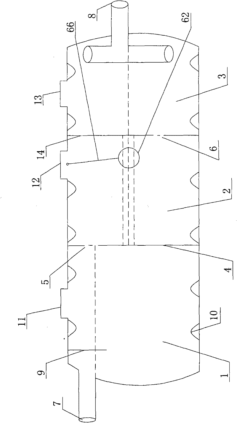
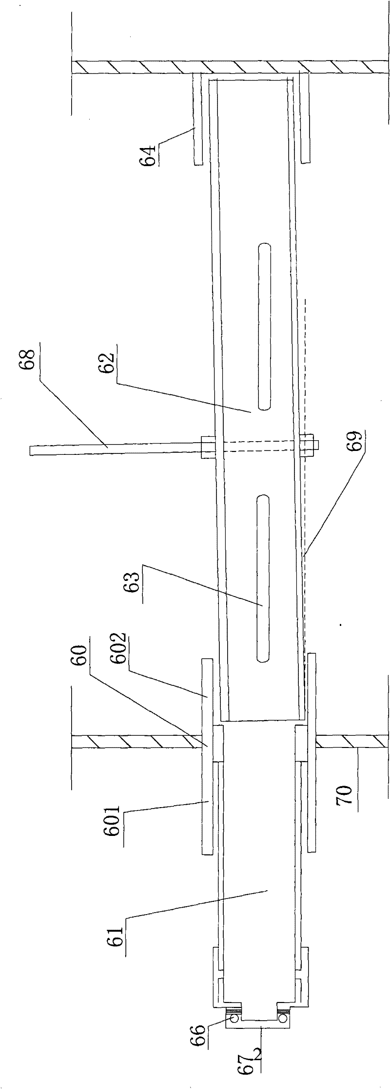
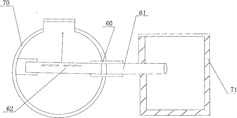
[0023] figure 1 , figure 2 and image 3 A specific embodiment of the oil-water separation tank of the present invention is given. The oil-water separation tank of the present invention is a sealed cylindrical overall structure, which includes a water inlet 7 separated by a partition 4. The water inlet chamber 1, the oil-water separation chamber 2 and the water outlet chamber 3 provided with a water outlet 8, the oil-water separation tank 2 are provided with rotating oil collecting pipes 62 installed obliquely on both sides of the pool body through mounting parts, and after the oblique installation The range of the tangent value of the angle 69 formed by the rotating oil collecting pipe and the horizontal direction is 0.5%-5%, and the preferred value is 1%. An operating rod 68 and two An oil inlet 63, when the rotating oil collecting pipe 62 rotates to the oil discharge state, the oil inlet 63 is parallel to the grease layer and is on the same level as the grease layer. The...


PUM


Abstract

The invention relates to an oil-water separation tank, which is of the sealed tank body structure and comprises a water inlet cabin, an oil-water separation cabin and a water outlet cabin that are separated by clapboards, wherein the water inlet cabin is provided with a water inlet; the water outlet cabin is provided with a water outlet; the oil-water separation tank is internally provided with rotating oil-collecting pipes arranged on the two sides of a tank body slantingly by installation parts; the middle part of the rotating oil-collecting pipe is provided with at least one oil inlet and at least one operating rod; and when the rotating oil-collecting pipes rotates to the oil discharge state, the oil inlet is parallel to a lipid layer on the same plane. The oil-water separation tank solves the technical problems of slack oil discharging of the oil-collecting pipes and complex structure, and is particularly suitable for treating the oily waste water in the catering industry.

Description

technical field [0001] The invention relates to a sewage treatment equipment, in particular to an oil-water separation device for treating oily sewage of catering. Background technique [0002] The wastewater discharged from restaurants, guesthouses, schools, enterprises, government agencies and other large catering establishments contains a large amount of oil. If it is directly discharged into urban sewage pipes, it will not only cause greater pollution, but also increase the difficulty of sewage treatment. At the same time, the oil contains a lot of organic components, which are directly discharged into the sewage pipes to cause a waste of resources. Therefore, before the catering sewage containing a large amount of oil is discharged into the urban sewage pipeline, the oil can be extracted through the oil-water separation device, which is convenient for waste to be reused. For example, the collected oil can be used as a chemical raw material. [0003] Traditional grease ...

Claims


Application Information

Patent Timeline
Patent Type & Authority Patents(China)
IPC IPC(8): B01D17/032C02F1/40
Inventor 陈星存
Owner 陈星存
Why Eureka
Try Eureka