
Elastic split type fastener of medium and low speed magnetic suspension rail

A maglev track and separate technology, applied in the direction of tracks, roads, buildings, etc., can solve the problems of lack of feasibility of gauge adjustment, poor vertical and horizontal adjustment ability of rail rows, failure to solve two-way vibration reduction, etc., to achieve good Maintenance and repairability, reduction of double impact, and simple structure

Active Publication Date: 2013-01-02
CHINA RAILWAY ERYUAN ENG GRP CO LTD
View PDF7 Cites 10 Cited by
  • Summary
  • Abstract
  • Description
  • Claims
  • Application Information

AI Technical Summary

Problems solved by technology

(2) The rail row of medium and low speed maglev transit can be regarded as an overall structure, which is firmly connected and has large longitudinal and lateral rigidity, so it does not need to be considered and does not have the feasibility of gauge adjustment
This technology directly connects the fastener screw with the support frame pre-buried in the track beam body by welding, which is a non-separate fastening method; although the fastener is firmly connected and has high reliability, it also has poor vertical and horizontal adjustment capabilities of the rail row. And failed to solve the problem of two-way vibration reduction

Method used


Image

  • Elastic split type fastener of medium and low speed magnetic suspension rail
  • Elastic split type fastener of medium and low speed magnetic suspension rail
  • Elastic split type fastener of medium and low speed magnetic suspension rail

Examples


Embodiment Construction

[0023] The present invention will be further described below in conjunction with the accompanying drawings and embodiments.

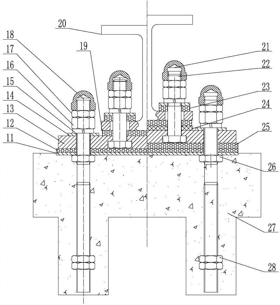
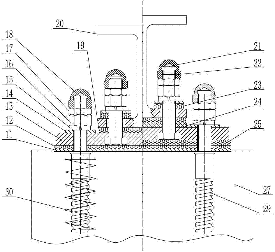
[0024] refer to Figure 1 to Figure 6 , the middle and low-speed maglev track elastic split fasteners of the present invention firmly connect the rail row composed of H-shaped steel sleepers 20 with the rail support platform 27 . It includes two sets of connecting bolt assemblies arranged at intervals in the transverse direction, and connects the H-shaped steel sleeper 20 with the connecting plate 13 as a whole. Between the bottom plate of the pillow 20 and the connecting plate 13, an elastic backing plate 19 under the pillow is arranged, and the bottom plates on both sides of the H-shaped steel sleeper 20 are provided with connecting bolt oblong holes 20a extending along the line direction for the upper part of the connecting bolt assembly to pass through. It also includes two sets of anchor bolt assemblies arranged at intervals in the transverse dire...


PUM


Abstract

An elastic split type fastener of a medium and low speed magnetic suspension rail has enough strength and buckling pressure, has large rail vertical, transverse and longitudinal adjusting capacity simultaneously provides rail elasticity and achieves bidirectional vibration attenuation. The elastic split type fastener comprises two groups of connection bolt assemblies arranged transversely at intervals and two groups of anchoring bolt assemblies transversely arranged at intervals, wherein the connection bolt assemblies integrate an H-shaped steel pillow with a connection board, vibration attenuation gaskets are arranged on the contact surfaces of the connection bolt assemblies and the H-shaped steel pillow, an under-pillow elastic cushion plate is arranged between a base plate of the H-shaped steel pillow and the connection board, and connection bolt long round holes extending along the circuit direction and used for enabling the upper portions of the connection bolt assemblies to penetrate through are arranged on the bottoms on two sides of the H-shaped steel pillow; and the anchoring bolt assemblies integrate the connection board and a support rail table, the lower portions of the anchoring bolt assemblies are connected with the support rail table in anchoring mode, a buffering cushion plate is arranged between the connection board and an iron cushion plate at the top surface of the support rail table, and anchoring bolt long round holes extending along the direction perpendicular to the circuit and used for enabling the upper portions of the anchoring bolt assemblies to penetrate through are arranged on the connection board.

Description

technical field [0001] The invention relates to the field of maglev rails, in particular to an elastically separate fastener for a medium-low speed maglev rail and a rail support structure for connecting a row of medium-low speed maglev rails and a rail support structure and an adjustment method thereof. Background technique [0002] Medium and low-speed maglev transportation has the characteristics of strong climbing ability, small turning radius, strong line adaptability, low noise, small vibration, energy saving and environmental protection, beautifying the urban environment, low construction cost, and easy implementation. It is suitable for urban areas and close-distance cities It is a safe, reliable and environment-friendly new urban rail transit system. [0003] Medium and low-speed maglev is an attraction maglev system under constant guidance. It uses the levitation electromagnet placed under the guide rail on the vehicle to energize and excite to generate an electric...

Claims


Application Information

Patent Timeline
Patent Type & Authority Applications(China)
IPC IPC(8): E01B25/30
Inventor 姚力庞玲蔡文锋张雷刘大园江万红易佳俊徐锡江邓存宥柏云吴春雷李春霞车晓娟吴承锦翟淼刘伟丁国富马晓杰姬广平
Owner CHINA RAILWAY ERYUAN ENG GRP CO LTD
Learn More