
Secondary ejecting mechanism and laminated injection die adopting same

A technology of secondary ejection and injection mold, applied in the field of ejector mechanism, can solve problems such as poor practicability, oscillation, and inability to provide upward power, so as to save manufacturing costs, ensure appearance quality, and improve injection molding production efficiency. Effect

Active Publication Date: 2013-02-06
QINGDAO HAIER MOLDS
View PDF6 Cites 3 Cited by
  • Summary
  • Abstract
  • Description
  • Claims
  • Application Information

AI Technical Summary

Problems solved by technology

This simple secondary ejection mechanism includes a thimble, a base plate, a panel and a B plate. A rotating shaft is fixed on the base plate, and a rotating block is sleeved on the rotating shaft. The ejector pin is fixed on one end of the rotating block, and the other end of the rotating block is fixed with a There is a spring on the accelerator needle. Although the secondary ejection mechanism can play a certain auxiliary role in the process of mold opening, it is due to the acceleration needle that provides power for the rotating block and the output power of the rotating block. The thimble is fixedly connected to the rotating block, so during the rotation of the rotating block, the accelerator pin and the thimble will swing, which cannot normally provide upward power for the mold opening process, and its practicability is not strong

Method used


Image

  • Secondary ejecting mechanism and laminated injection die adopting same
  • Secondary ejecting mechanism and laminated injection die adopting same
  • Secondary ejecting mechanism and laminated injection die adopting same

Examples


Embodiment Construction

[0026] The technical solutions of the present invention will be further described below in conjunction with the accompanying drawings and through specific implementation methods.

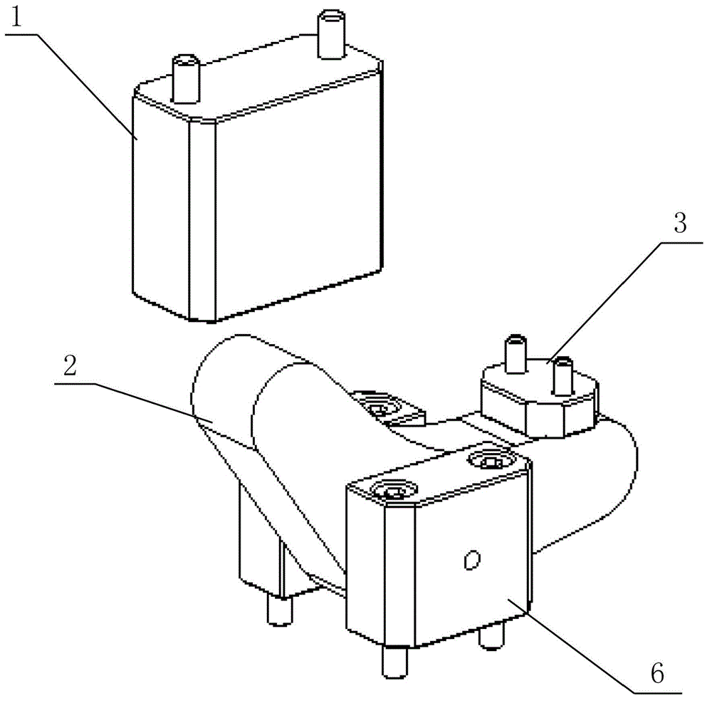
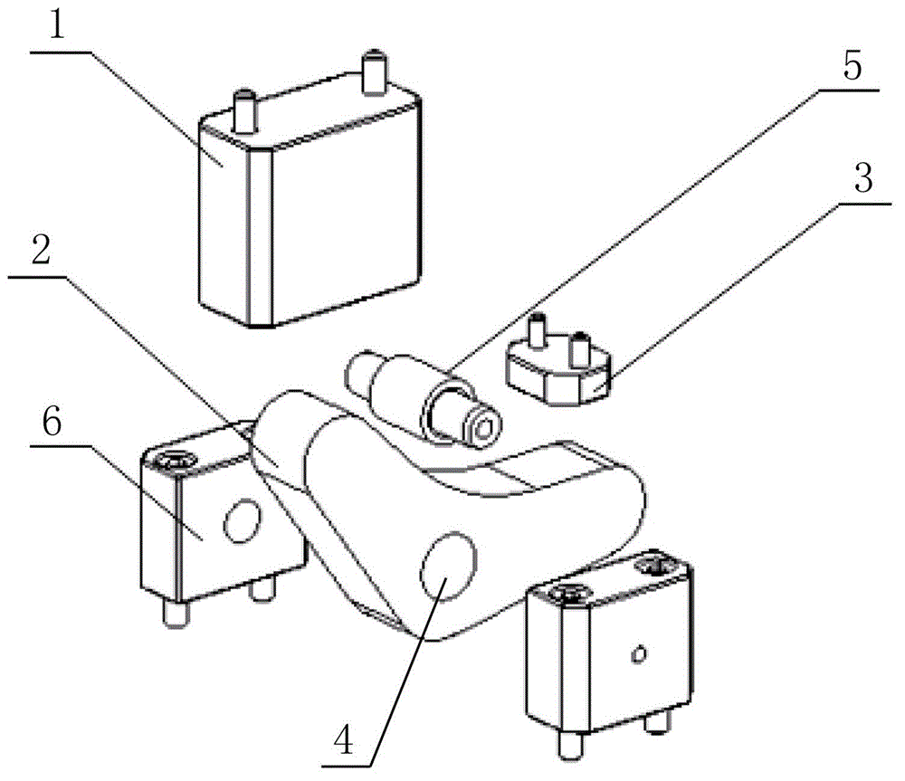
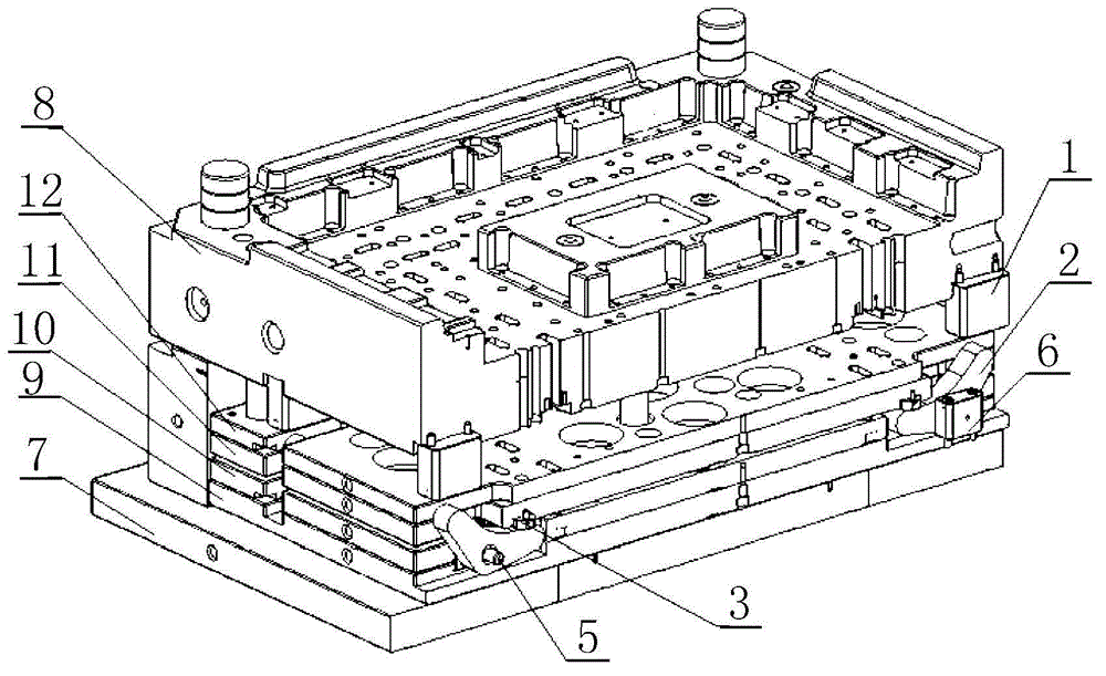
[0027] Such as Figure 1~2 As shown, a secondary ejection mechanism is suitable for the secondary ejection of the injection mold, which includes a limit block 1 and a seesaw 2, wherein the limit block 1 is fixed on the lower template of the injection mold The seesaw 2 includes a first arm 21 and a second arm 22 at an angle to each other, preferably, the angle between the first arm 21 and the second arm 22 is greater than 90 degrees, and the seesaw 2 is rotatable Set on the first ejector plate of the mold; the first arm 21 is located at the lower part of the limit block 1, the second arm 22 is located at the lower part of the second ejector plate, and the first arm 21 is used to receive the limit block 1 provides the force opposite to the mold opening direction, and the second arm 22 is used to prov...


PUM


Abstract

The invention discloses a secondary ejecting mechanism and a laminated injection die adopting the same. The secondary ejecting mechanism is suitable for secondary ejection of an injection die, and comprises a limited block and a seesaw, wherein the limited block is fixed on a lower die plate of the injection die; the seesaw comprises a first support arm and a second support arm; an included angle is formed between the first support arm and the second support arm; the seesaw is arranged on a first ejection plate in a rotatable manner; the first support arm is positioned at the lower part of the limited block; the second support arm is positioned at the lower part of a second ejection plate; the first support arm is used for receiving the downward acting force provided by the limited block; the second support arm is used for providing the upwards power provided by the second ejection plate; and the second ejection plate is positioned at the upper part of the first ejection plate, and can move vertically relative to the first ejection plate. The number of the dies of the secondary ejection mechanisms is increased, the problems of white stress marks on the surface and die holding of the product can be solved, the production efficiency is improved, and the manufacturing cost of the die is reduced.

Description

technical field [0001] The invention relates to an ejection mechanism of a laminated injection mold, in particular to a secondary ejection mechanism and a laminated injection mold adopting the mechanism. Background technique [0002] With the development of society, consumers have higher and higher requirements on the performance and appearance of products, which requires us to improve the refinement of product manufacturing. [0003] In the process of ejecting the product by the laminated injection mold, if the plastic product is closed around and has deep ribs on the inner circumference, when the product is ejected in one-time use, the top surface of the product will be white or damaged. It is difficult to take out the product when it is hugged on the rear mold, which will directly affect the appearance quality of the product, cause the increase of unqualified products, and reduce the production efficiency of the product. [0004] In order to solve the above problems, sci...

Claims


Application Information

Patent Timeline
IPC IPC(8): B29C45/40B29C45/26
Inventor 王涛黄俊张向华朱运成王彬
Owner QINGDAO HAIER MOLDS
Learn More