
Pressure bearing device suitable for pressurized coring tool
A technology of pressure-bearing devices and tools, which is applied in the field of pressure-bearing devices, can solve problems such as damage to the performance of the outer cylinder, achieve automatic pressure relief, improve work efficiency and reliability, and facilitate production
- Summary
- Abstract
- Description
- Claims
- Application Information
AI Technical Summary
Problems solved by technology
Method used
Image

Examples
Embodiment 1
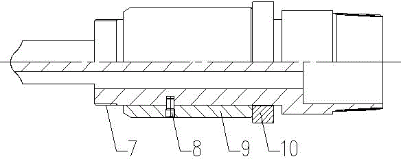
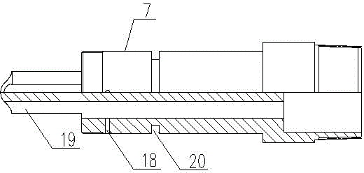
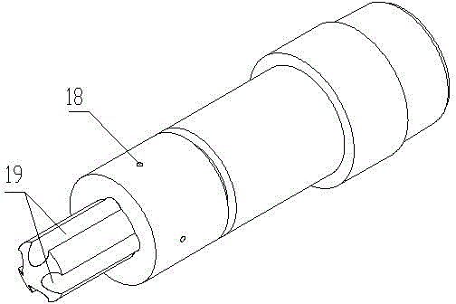
[0035] A pressure-bearing device suitable for pressurized coring tools, including a pressure-bearing assembly and a pin component, the pressure-bearing assembly includes a pressure-bearing piston 7 and a pressure-bearing sleeve 9 sleeved on the pressure-bearing piston 7, The pin part includes a shear pin 8, the upper end of the pressure-bearing piston 7 is limited in the pressure joint 5 in the hexagonal sleeve 3 by the pressure-bearing steel ball 6, and the pressure-bearing steel ball 6 can transmit the pressure to the pressure-bearing piston 7, The lower end is the connection end connected with the rotating assembly 12, the pressure bearing sleeve 9 is fixedly connected with the pressure bearing piston 7 through the shear pin 8, the lower end of the pressure bearing sleeve 9 is limited on the outer cylinder short 11, and the upper end of the pressure bearing piston 7 is provided with A sand release hole 18 and a flow channel 19 communicated with the inner cavity of the pressu...
Embodiment 2
[0046] In this embodiment, when the present invention is applied to a pressurized coring tool, it will be described in detail in conjunction with other components of the pressurized coring tool.
[0047] The pressurized coring tool involved includes an upper joint 1, a hexagonal rod 2, a hexagonal sleeve 3, an outer cylinder short 11, an outer cylinder 13, a difference short 15, an inner cylinder assembly 14, and a core bit 17. The sleeve 3 is connected to the outer cylinder 13 through the outer cylinder short 11, the outer cylinder 13 is connected to the differential short 15, and the differential short 15 is connected to the core bit 17, and also includes a pressure bearing device, a rotating assembly 12 and a core claw Assembly 16.
[0048] The specific description of the pressure-bearing device is as follows:
[0049] The pressure-bearing device includes a pressure-bearing assembly and a pin component. The pressure-bearing assembly includes a pressure-bearing piston 7 and...
Embodiment 3
[0072] In this embodiment, when the present invention is applied to a pressurized coring tool, the connection and working process of the pressurized coring tool are described in detail.
[0073] The pressure-bearing piston is arranged in the middle section of the pressurized coring tool, and a sand discharge hole 18 and a flow channel 19 are arranged at the front end of the pressure-bearing piston 7, and four flow channels 19 are arranged at the front end of the pressure-bearing piston 7, and the flow channel 19 is a groove shape, and three sand discharge holes 18 are arranged on the circumference of the pressure-bearing piston 7 at the rear end of the flow channel 19; the upper end of the pressure-bearing piston 7 is blocked by the pressure-bearing steel ball 6 in the pressure joint 5 of the coring tool , the upper end of the pressure joint 5 is a hexagonal rod 2, and a rubber seal 4 is arranged between the hexagonal rod 2 and the pressure joint 5; the hexagonal rod 2, the pre...
PUM
 Abstract
Description
Claims
Application Information