Transformer diagnosis system and diagnosis method

A diagnostic system and diagnostic method technology, applied in the field of transformers, can solve the problems of small macroscopic feature quantity, abnormal temperature, affecting the accuracy of measurement, etc., and achieve the effects of small external interference, high signal-to-noise ratio and good reliability.

Inactive Publication Date: 2013-12-25
威胜百楚电力科技有限公司
View PDF9 Cites 18 Cited by
  • Summary
  • Abstract
  • Description
  • Claims
  • Application Information

AI Technical Summary

Problems solved by technology

There are many power failure test methods for power equipment in the International Electricity Standard (IEC), which usually need to be carried out under power failure conditions, which cannot reflect the arc discharge and abnormal vibration state that may occur under working conditions. Multiple transformer damage accidents
There are also many online test methods for power equipment at home and abroad. The effect of ultrasonic partial discharge method is not obvious in practice and online detection is still under discussion; the online method of insulating oil chromatography is limited to chemical analysis and the condition of insulating oil; the limitation of infrared imaging thermometry Due to abnormal temperature, the internal defects of the equipment cannot be detected; the online dielectric loss method of capacitive substation equipment has not yet solved the "distortion" problem of the sampling signal of the mutual inductance type sensor, etc. Although these methods have the advantages of good real-time performance, but Because the macro-characteristics reflecting insulation defects are too small, they are susceptible to interference from on-site electric fields and magnetic fields, or due to the complex structure of the transformer, the measurement accuracy is seriously affected, which greatly reduces the reliability of the monitoring results of these methods.

Method used


Image

  • Transformer diagnosis system and diagnosis method

Examples


Embodiment Construction

[0014] The implementation of the present invention will be described in detail below in conjunction with the accompanying drawings, but they do not constitute a limitation to the present invention, they are only examples, and at the same time, the advantages of the present invention will become clearer and easier to understand.

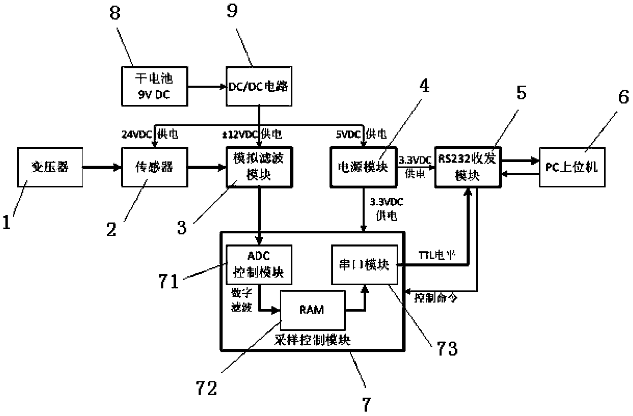
[0015] Referring to the accompanying drawings, it can be seen that the transformer diagnosis system of the present invention includes a transformer 1, a sensor 2, an analog filter module 3, a power supply module 4, an RS232 transceiver module 5, a PC upper computer 6, a sampling control module 7, a battery 8 and a DC-DC circuit 9. The battery 8 is connected to the input end of the DC-DC circuit 9, and the output end of the DC-DC circuit 9 is respectively connected to the sensor 2, the analog filter module 3 and the power supply module 4, and the analog filter module 3 and the power supply The output end of module 4 is all connected with sampling contro...


PUM


Abstract

The invention discloses a transformer diagnosis system which comprises a transformer, a sensor, an analog filter module, a power supply module, an RS232 transceiving module, a PC upper computer, a sampling control module, a battery and a DC-DC circuit. According to the invention, acoustic features generated during transformer failure detection in a frequency range of 20Hz-10kHz are compared to diagnose the operation state of a transformer; and the magnetically mounted vibration or acoustic sensor clings to the surface of the transformer to perform signal monitoring, is high in signal to noise ratio and convenient to mount, is less influenced by external interference, does not influence normal operation of the transformer and does not cause damage to the transformer structure. The invention also discloses a transformer diagnosis method using the transformer diagnosis system.

Description

technical field [0001] The invention relates to the technical field of transformers, in particular to a transformer diagnosis system, and also relates to a diagnosis method using the transformer diagnosis system. Background technique [0002] The echolocation technology of sound waves and vibration waves has broad application prospects in the power industry, especially when transformers are in normal operation, because the alternating current passes through the windings of the transformer to generate periodically changing alternating magnetic flux in the iron core, causing the iron core The vibration of the transformer will emit a uniform humming sound. Once the iron core winding in the transformer fails or arc discharge occurs, its acoustic characteristics will also change accordingly and present certain inherent characteristics. Therefore, the acoustic characteristic signal of transformer equipment can represent the operating state of the transformer. [0003] At present,...

Claims


Application Information

Patent Timeline
Patent Type & Authority Applications(China)
IPC IPC(8): G01R31/02G01H17/00
Inventor 邹云屏欧阳军
Owner 威胜百楚电力科技有限公司
Why Eureka
Try Eureka