Electronic expansion valve

A technology of electronic expansion valve and valve seat, which is applied in the direction of valve details, valve devices, valve energy absorption devices, etc., can solve the problems of high noise and achieve the effect of eliminating noise, eliminating the need for welding, and reducing installation steps

Active Publication Date: 2013-02-06
ZHEJIANG DUNAN HETIAN METAL CO LTD
View PDF3 Cites 15 Cited by
  • Summary
  • Abstract
  • Description
  • Claims
  • Application Information

AI Technical Summary

Problems solved by technology

[0005] The invention provides an electronic expansion valve to solve the problem of high noise of the existing electronic expansion valve

Method used


Image

  • Electronic expansion valve
  • Electronic expansion valve
  • Electronic expansion valve

Examples


Embodiment Construction

[0030] Unless otherwise specified, the terms used in the context of the present invention have the meanings given below. Other terms not specifically given herein have their usual meanings in the art.

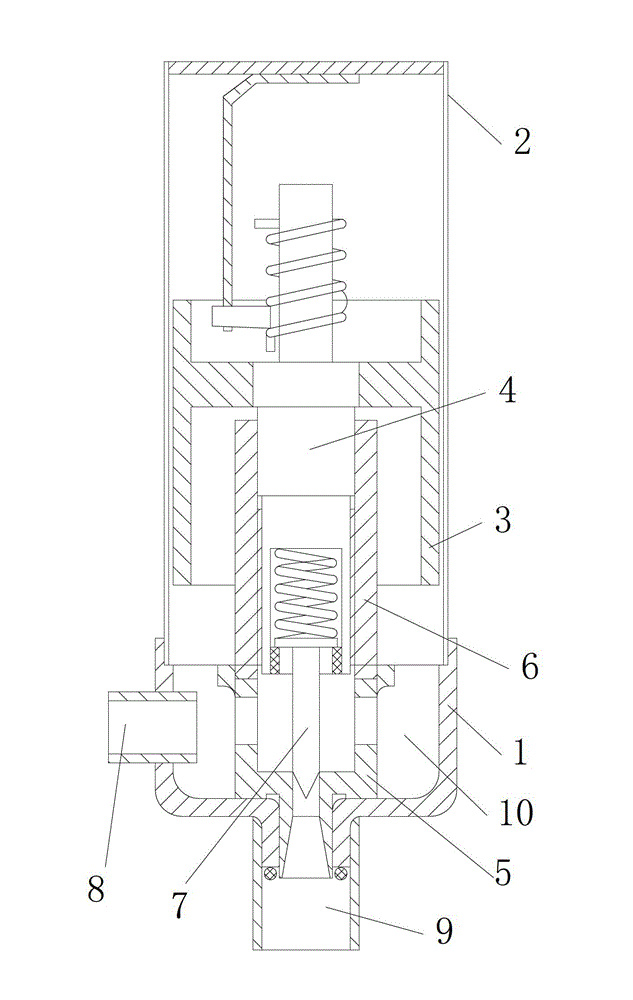
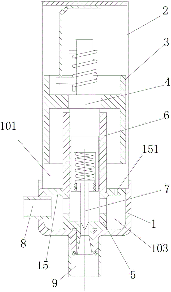
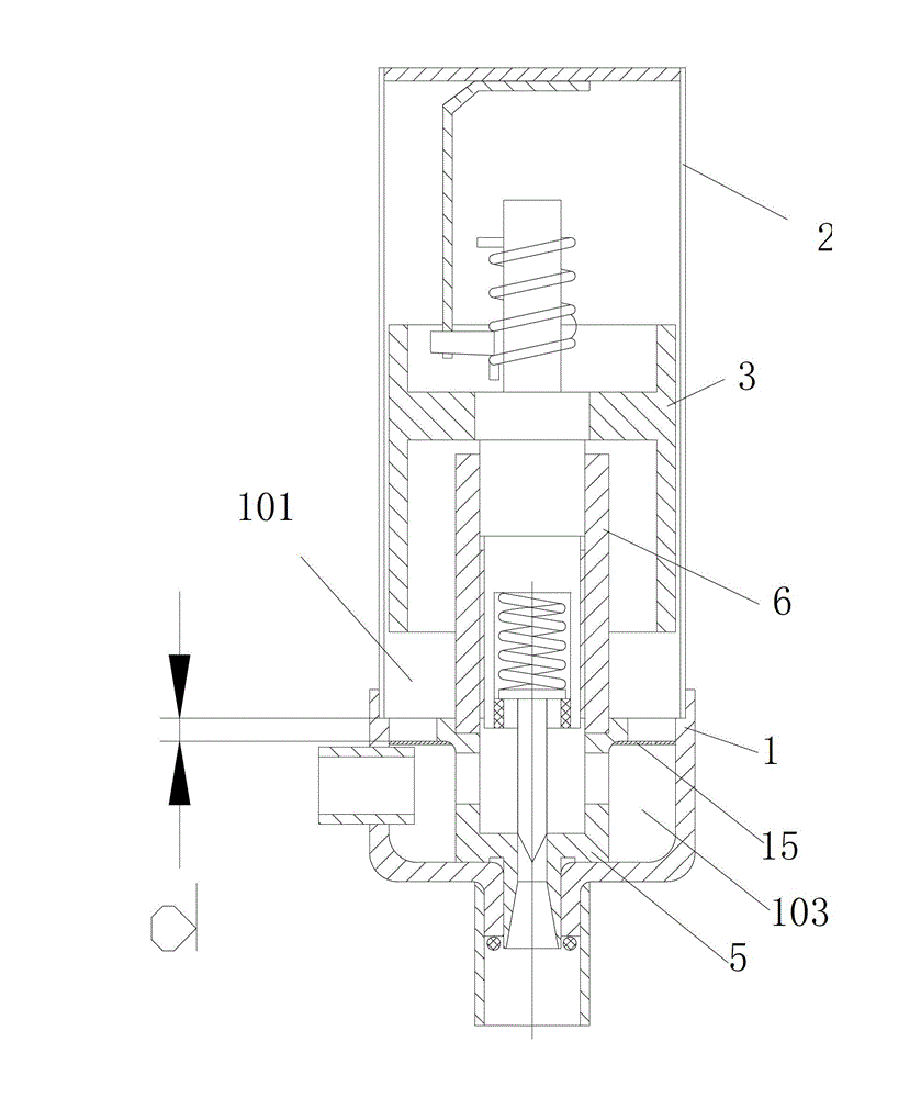
[0031] Such as Figure 2 to Figure 8 As shown in the drawings, the electronic expansion valve according to the embodiment of the present invention includes: a valve body 1, a sleeve 2 connected to the upper end of the valve body 1, a valve seat 5 arranged in the valve body, and a nut 6 connected to the upper end of the valve seat 1. The magnetic rotor 3 arranged outside the nut and cooperating with the upper part of the nut through the screw rod 4 . A cavity is formed between the inner wall of the sleeve and the valve body and the nut and the outer wall of the valve seat. The electronic expansion valve can also include: an inlet pipe 8 and an outlet pipe 9 arranged on the valve body. The above-mentioned structure can adopt the structure of the existing electronic expansion va...


PUM


Abstract

The invention provides an electronic expansion valve which comprises a valve body (1), a sleeve (2) connected to the upper end of the valve body (1), a valve seat (5) arranged in the valve body, a nut (6) connected with the upper end of the valve seat and a magnetic rotor (3) which is arranged outside the nut and matched with the upper part of the nut through a screw rod (4), wherein a cavity is formed between the inner walls of the sleeve (2) and the valve body (1) and the outer walls of the nut (6) and the valve seat (5). The electronic expansion valve is characterized by also comprising a baffle plate (15) and a damping channel (151), wherein the baffle plate is arranged in the cavity to divide the cavity into an upper cavity (101) and a lower cavity (103); and the damping channel (151) is communicated with the upper cavity and the lower cavity. According to the electronic expansion valve, because the cavity used for accommodating fluid is divided into the upper cavity and the lower cavity through the baffle plate, and intense interference to the magnetic rotor of fluid pulse is reduced through the damping channel, resonance is prevented, and noise is reduced or eliminated.

Description

technical field [0001] The invention relates to the refrigeration field, in particular to an electronic expansion valve. Background technique [0002] The electronic expansion valve uses the principle of a stepping motor to drive the magnetic rotor part to rotate forward and reverse with a coil, and converts the rotation of the magnetic rotor part into the up and down movement of the screw, and the screw drives the valve needle connected to it to rise or Decrease to control the flow rate of the electronic expansion valve. [0003] Such as figure 1 As shown, the existing electronic expansion valve includes: a valve body 1 , a valve seat 5 arranged on the bottom wall of the valve body and a nut 6 installed on the upper part of the valve body. The nut is provided with a screw 4 (lead screw), and the nut 6 is provided with a magnetic rotor 3, and the magnetic rotor 3 is provided with a sleeve 2 covering the upper part of the valve body, and the sleeve 2 surrounds the nut 6, th...

Claims


Application Information

Patent Timeline
Patent Type & Authority Applications(China)
IPC IPC(8): F16K47/02
Inventor 王定军
Owner ZHEJIANG DUNAN HETIAN METAL CO LTD
Why Eureka
Try Eureka