Hinge for furniture

A technology for hinges and furniture, applied in the field of hinges, can solve the problems of strong contact pressure, wear of torsion springs and parts, affecting the life of torsion spring hinges, etc., to reduce pressure, reduce rigid friction, and open and close smoothly and reliably.

Active Publication Date: 2013-03-06
伍志勇
View PDF8 Cites 9 Cited by
  • Summary
  • Abstract
  • Description
  • Claims
  • Application Information

AI Technical Summary

Problems solved by technology

However, because the diameter of the torsion spring steel wire is very small, the contact portion between the support leg of the torsion spring and the part is very small, almost a point contact, so the pressure at the contact is strong, resulting in serious wear between the torsion spring and the part, affecting the torsion spring. even the life of the entire hinge

Method used


Image

  • Hinge for furniture
  • Hinge for furniture
  • Hinge for furniture

Examples


no. 1 example

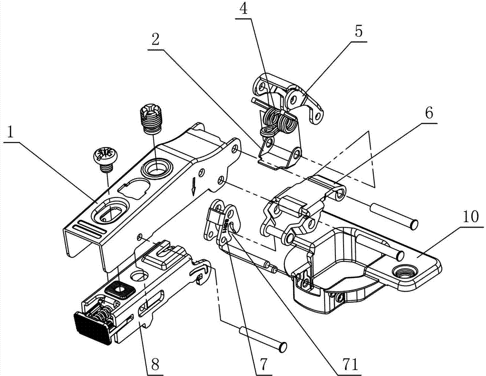
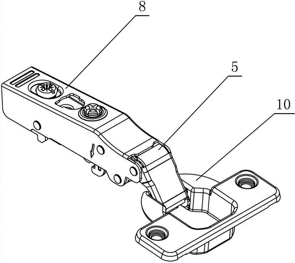
[0026] see figure 1 - Figure 5 , the hinge for this furniture, including the connecting arm 1 and the movable cup holder 10 connected by the swing arm, the hinge is provided with a torsion spring 4 that at least generates an opening and closing force on the movable cup holder 10, and the connection between the torsion spring 4 and the inner swing arm 6 There is a wear-reducing block A 2 between them, and the wear-reducing block A 2 is slidably connected with the inner swing arm 6 during the opening and closing of the hinge; the wear-reducing block A 2 is provided with a fixed part, and a pin shaft is interspersed on the fixed part and fixed on the outer swing on arm 5.

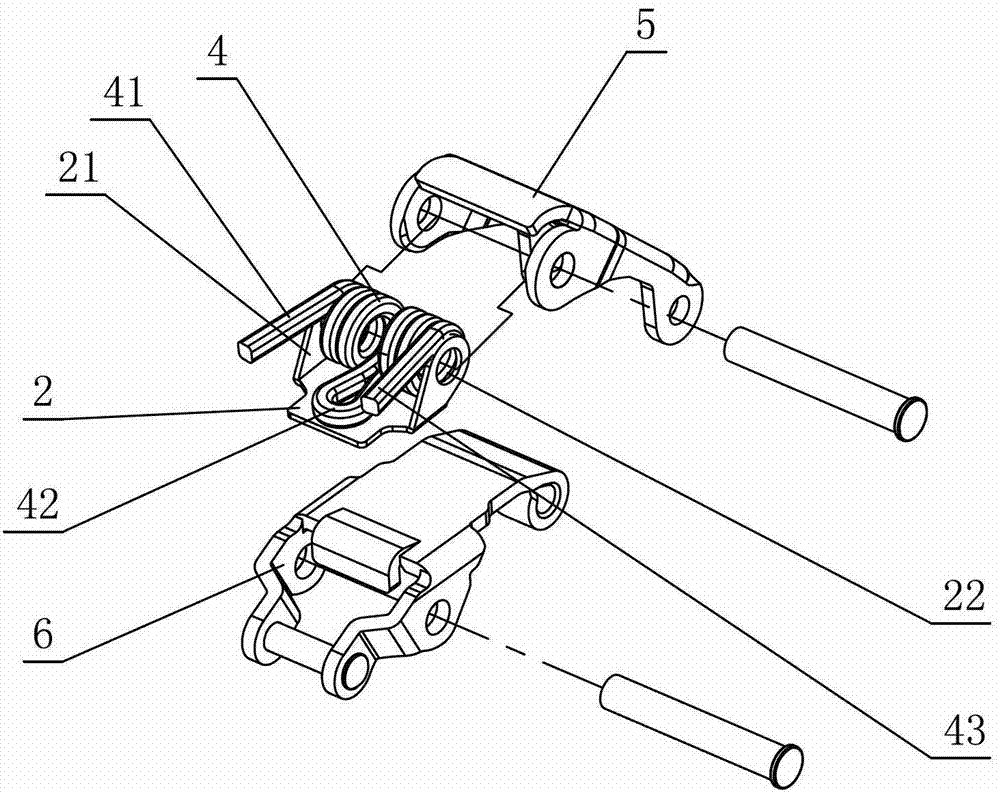
[0027] The components of this hinge are combined as follows: the swing arm includes an outer swing arm 5 and an inner swing arm 6; the torsion spring 4 is positioned at the hinge of the connecting arm 1 and the outer swing arm 5 through a pin; the torsion spring 4 includes a head support foot 41 , the middl...

no. 2 example

[0030] see Figure 6 - Figure 8 , the hinge for this furniture, the wear-reducing block 3B is a plastic part, in the shape of a groove, and is provided with longitudinal side parts 31 on both sides, and a transverse through hole 32 is provided on the longitudinal side part 31; the wear-reducing block B 3 is placed on the torsion spring 4, the slot 33 is fitted into one end of the inner swing arm 6, and a pin shaft is inserted through the transverse through hole 32 to be fixedly arranged at the hinge of the inner swing arm 6 and the connecting arm 1. Other unmentioned parts are the same as the first embodiment.

no. 3 example

[0032] see Figure 9 - Figure 11 , the hinge used for this furniture, the wear-reducing block includes wear-reducing block A 2 and wear-reducing block B 3; the wear-reducing block A 2 is a plastic part or a metal part, in the shape of a plate or a block, and is provided with longitudinal side parts on both sides 21. The longitudinal side 21 is provided with a transverse through hole 22; the anti-friction block A2 is placed under the torsion spring 4, and the pin shaft is interspersed in the transverse through hole 22 and fixed at the hinge of the outer swing arm 5 and the connecting arm 1; Abrasive block B 3 is a metal piece or a plastic piece, which is in the shape of a groove, and is provided with longitudinal side portions 31 on both sides, and a transverse through hole 32 is provided on the longitudinal side portion 31; the wear-reducing block B 3 is placed on the wear-reducing block A 2 Below, the slot 33 is fitted into one end of the inner swing arm 6 , and a pin shaft...


PUM


Abstract

The invention discloses a hinge for furniture. The hinge comprises a connecting arm and a movable cup seat, which are connected through a swing arm. A torsion spring at least generating opening and closing action force on the movable cup seat is arranged in the hinge. The hinge is characterized in that an anti-friction block is arranged between the torsion spring and an inner swing arm, and is in sliding connection with the inner swing arm in the opening and closing processes of the hinge; a fixing part is arranged on the anti-friction block; and a pin shaft is inserted into the fixing part, and is fixedly arranged on an outer swing arm or the inner swing arm. The anti-friction block is arranged between the torsion spring and the inner swing arm, and is limited and fixedly arranged on the outer swing arm and / or the inner swing arm through the fixing part; the anti-friction block contacts with a part in the hinge through a plane, so that the contact between the anti-friction block and the part of the hinge is linear contact or surface contact, the pressure of a contact part is greatly reduced, rigid friction between the torsion spring and the part of the hinge is reduced, abrasion is reduced, the service life of the product is prolonged, and the aim of smoothly and reliably opening and closing the hinge is also fulfilled.

Description

technical field [0001] The invention relates to a hinge, in particular to a hinge for furniture. Background technique [0002] Chinese Patent Document No. CN1873178 disclosed a hinge device on December 6, 2006, which has: an elongated first body installed on the furniture body; a cover-shaped second body installed on the door; the second body The first and second chain links rotatably connected to the first body; and the torsion spring, one end of the torsion spring pushes the spring receiving plate of the first chain link, thereby, the second body faces the first The main body rotates and applies force, one end of the torsion spring is disposed between the side wall of the first main body and the side wall of the second link, the gap between the spring receiving plate and the side wall of the first main body, and the gap between the spring receiving plate and the side wall of the second link. The gaps between the side walls of the second link are all smaller than the line ...

Claims


Application Information

Patent Timeline
Patent Type & Authority Applications(China)
IPC IPC(8): E05D3/02E05D11/00E05F1/12
Inventor 伍志勇
Owner 伍志勇
Why Eureka
Try Eureka