Supercharge Your Innovation With Domain-Expert AI Agents!

Optical fiber connecting component

A technology of optical fiber connecting components and connecting parts, which is applied in the direction of coupling of optical waveguides, etc., can solve the problems of crashing the positioning feet, affecting the transmission of optical signals, and the inability of the USB female interface to be accurately aligned.

Inactive Publication Date: 2013-03-06
HONG FU JIN PRECISION IND (SHENZHEN) CO LTD +1
View PDF5 Cites 2 Cited by
  • Summary
  • Abstract
  • Description
  • Claims
  • Application Information

AI Technical Summary

Problems solved by technology

[0004] However, when a user connects an ordinary USB male interface to a USB female interface that can be connected to a USB male interface of Light Peak technology, since the ordinary USB male interface is not provided with a positioning hole for accommodating the positioning feet, it is very easy to hit or even Crashing the positioning feet on the USB female interface, causing the USB female interface to be incorrectly aligned when connected to the USB male interface using Light Peak technology, thereby affecting the transmission of optical signals

Method used


Image

  • Optical fiber connecting component
  • Optical fiber connecting component
  • Optical fiber connecting component

Examples


Embodiment Construction

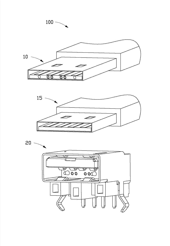
[0016] see figure 1 , is the optical fiber connection assembly 100 according to the first embodiment of the present invention, which includes a first male interface 10 , a second male interface 15 and a female interface 20 connected to the first male interface 10 or the second male interface 15 .

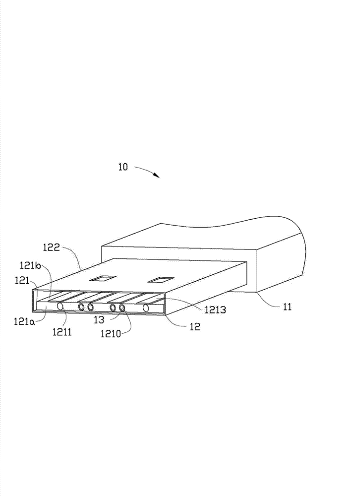
[0017] see figure 2 , the first male interface 10 includes a first holding portion 11 and a first connecting portion 12 disposed on the first holding portion 11 . The first connecting portion 12 includes a hollow first surrounding portion 122 and a first flat plate 121 disposed in the first surrounding portion 122 . The first flat plate 121 includes a first end surface 121 a away from the first holding portion 11 . The first end surface 121 a is provided with a plurality of first receiving holes 1210 for receiving the first optical fiber interface 13 . The first end surface 121a is further provided with a plurality of positioning holes 1211 . The distance from the first end sur...


PUM


Abstract

An optical fiber connecting component comprises a first male connector, a second male connector and a female connector. The first male interface comprises a first gripping part and a first connecting part. The first connecting part comprises a first encircling part and a first flat plate. A first end face of the first flat plate comprises a plurality of containing holes for containing a first optical fiber interface. The distance from the first end face to the first gripping part is L1. The second female connector comprises a second gripping part and a second connecting part. The second connecting part comprises a second encircling part and a second flat plate. The vertical distance from a second end face to the second gripping part is L2. The female connector comprises a first outer surface and a second outer surface. A containing cavity which comprises a bottom is reserved on the second outer surface. The vertical distance from the bottom to the second outer surface is L3. A plurality of containing holes for containing a second optical fiber interface are reserved at the bottom which is further provided with a plurality of positioning pins. The length, along the direction perpendicular to the bottom, of each positioning pin is L4, wherein L3=L1> / = (L2+L4).

Description

technical field [0001] The present invention relates to an optical fiber connection assembly. Background technique [0002] Currently, there are more and more types of computer hardware and digital products, such as keyboards, mice, cameras, MP3, etc. These products often need to be connected to a computer for use or file transfer. As a universal interface form, the USB interface is used in more and more products. [0003] Light Peak technology, a technology that applies optical fiber transmission to peripheral devices and computer data transmission, appeared in 2009. Optical fiber transmission replaces traditional data lines for data transmission, and the transmission speed will far exceed the existing data line transmission speed. The Light Peak interface uses the specifications of the ordinary USB interface and retains the metal sheet structure of the ordinary USB interface. The difference is that an optical fiber interface is added to the USB male interface and the USB...

Claims


Application Information

Patent Timeline
IPC IPC(8): G02B6/38
Inventor 吴开文
Owner HONG FU JIN PRECISION IND (SHENZHEN) CO LTD
Features
  • R&D
  • Intellectual Property
  • Life Sciences
  • Materials
  • Tech Scout
  • Unparalleled Data Quality
  • Higher Quality Content
  • 60% Fewer Hallucinations
Learn More