Eureka AIR delivers breakthrough ideas for toughest innovation challenges, trusted by R&D personnel around the world.

Burner combustion method

A combustion method and technology of a combustion device, which are applied in the field of burner combustion, can solve problems such as reduction and lack of practical value, and achieve the effect of reducing NOX

Inactive Publication Date: 2015-02-11
NIPPON SANSO CORP
View PDF10 Cites 0 Cited by
  • Summary
  • Abstract
  • Description
  • Claims
  • Application Information

AI Technical Summary

Problems solved by technology

[0014] However, in order to confirm the NO of these prior art, the inventors etc. X As a result of the review test to reduce the effect, it is known that some of the above-mentioned existing technologies have been recognized as NO X Reduction effect, but no reduction effect of practical value

Method used


Image

  • Burner combustion method
  • Burner combustion method
  • Burner combustion method

Examples


no. 1 approach

[0055]

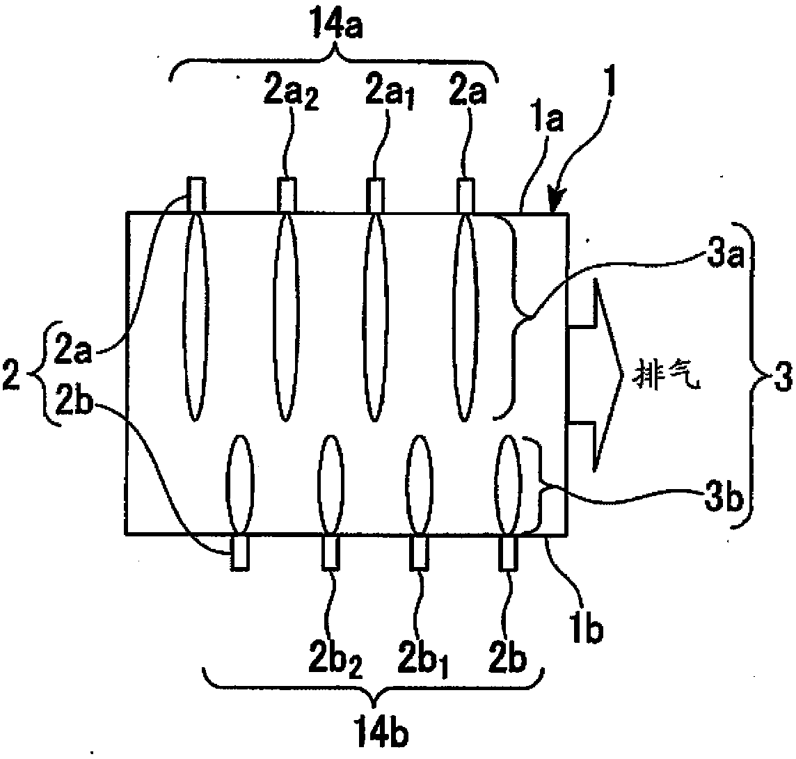
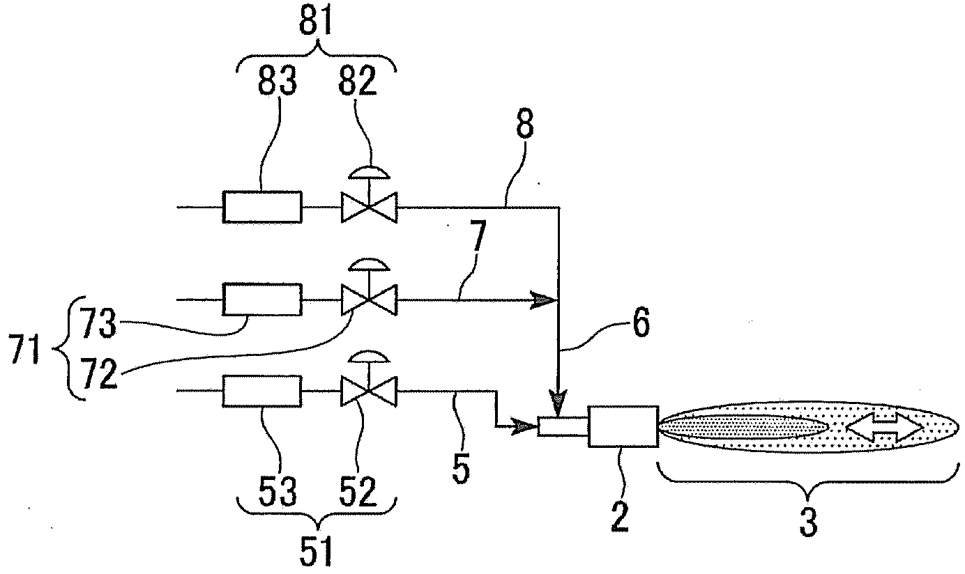
[0056] The combustion apparatus used in the first embodiment of the present invention such as figure 1 with figure 2 Shown is a structure including a furnace 1 , a burner 2 forming a combustion flame 3 in the furnace 1 , and various pipes 5 , 6 , 7 , and 8 for supplying a fuel fluid and an oxidant fluid to the burner 2 .

[0057] Such as figure 1 As shown, the furnace 1 may be a heating furnace or a melting furnace, and includes a side wall 1 a and a side wall 1 b extending in the longitudinal direction and arranged to face each other. A plurality of burners 2a are provided on the side wall 1a, and a plurality of burners 2b are also provided on the side wall 1b. Thus, the furnace 1 has a so-called side burner type structure in which burners 2a, 2b forming combustion flames 3a, 3b are provided on both side walls 1a, 1b in the longitudinal direction.

[0058] In addition, in the present embodiment, the number of burners 2a provided on the side wall 1a is the same as...

no. 2 approach

[0109] Next, a combustion method using the burner according to the second embodiment of the present invention will be described. In addition, this embodiment is a modified example of the first embodiment, and description of the same parts will be omitted.

[0110] This embodiment differs from the first embodiment in that a phase difference is provided in the pulsation cycle of adjacent burners 2 , and the others are the same as the first embodiment.

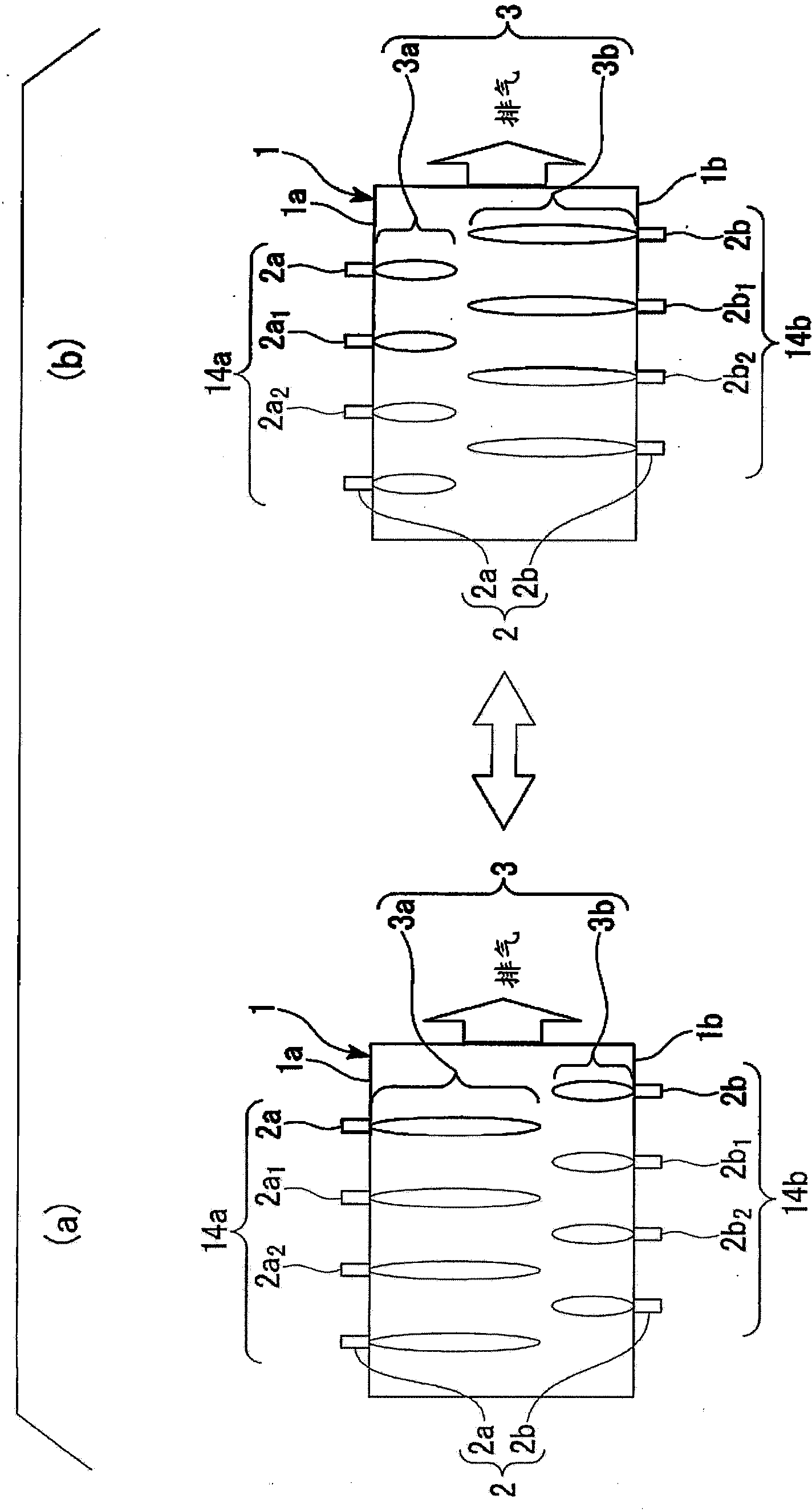
[0111] Such as Figure 4 (a) and Figure 4 As shown in (b), in this embodiment, a plurality of burners 2a and 2b are respectively provided on the side wall 1a and the side wall 1b. Only one burner 2 forms each burner array 24 . That is, each burner 2a provided on the side wall 1a forms a burner array 24a, and each burner 2b provided on the side wall 1b forms a burner array 24b, respectively.

[0112] In addition, in this embodiment, adjacent burners 2 are controlled so that the phase difference of the pulsation period is π. ...

no. 3 approach

[0119] Next, a combustion method using the burner according to the third embodiment of the present invention will be described. In addition, this embodiment is a modified example of the first embodiment, and description of the same parts will be omitted.

[0120] This embodiment differs from the first embodiment in that a difference is provided in the pulsation cycle of adjacent burners 2 , and the rest is the same as the first embodiment.

[0121] That is, if Image 6 As shown, in this embodiment, n burners 2a and 2b are respectively provided on the side wall 1a and the side wall 1b of the furnace 1 . Only one burner 2 forms each burner array 44 . That is, each burner 2a provided on the side wall 1a forms a burner array 44a, and each burner 2b provided on the side wall 1b forms a burner array 44b.

[0122] In addition, in this embodiment, it controls so that the phase difference with the pulsation period of the adjacent burner 2 may become 2π / n. For example, in the case w...


PUM


Abstract

A burner combustion method is employed in which at least two burners (2) are disposed opposite each other in a furnace (1) so as to cause combustion, the method comprising: cyclically changing at least one of a flow rate of a fuel fluid and a flow rate of an oxidant fluid supplied to the respective burners (2) while cyclically changing a concentration of oxygen in the oxidant fluid thereby cyclically changing an oxygen ratio obtained by dividing a supply oxygen amount by a theoretically required oxygen amount, whereby, the burners (2) are made to cause combustion in a cyclical oscillation state, wherein with respect to the cyclical change in an oscillation state of the burners (2), a phase difference is provided between a cyclical change in an oscillation state of at least one burner (2) and cyclical changes in oscillation states of other burners (2).

Description

technical field [0001] The invention relates to a combustion method of a burner. Background technique [0002] Now that we are vigorously promoting the earth's environment, with NO X The reduction of nitrogen oxides indicated is one of the important issues and an urgent task. as NO X Reduction methods, technologies related to generation suppression are particularly important, such as exhaust gas recirculation, lean combustion, rich-lean combustion, staged combustion, etc., which are widely used from industrial to civilian use. By applying these techniques the low NO X burner, NO X Countermeasures have progressed to some extent, but more effective NO X lowering method. [0003] NO obtained from previous research and development X As one of the reduction methods, there exists and is proposed a method of performing a temporal rich-lean combustion (hereinafter referred to as forced pulse combustion) even if the flow rate of air as a fuel or an oxidant changes periodically...

Claims


Application Information

Patent Timeline
Patent Type & Authority Patents(China)
IPC IPC(8): F23C15/00F23C99/00
CPCF23C2205/20F23N1/02F23C99/00F23C2205/10F23C5/28F23C15/00
Inventor 山本康之饭野公夫萩原义之羽路智之
Owner NIPPON SANSO CORP
Why Eureka
Eureka Blog
Learn More