Parametric Design Method of Level 1 Components for Aircraft Beams, Walls and Ribs
What is AI technical title?
AI technical title is built by Patsnap AI team. It summarizes the technical point description of the patent document.
A parametric design and parametric technology, applied in computing, electrical digital data processing, special data processing applications, etc., can solve problems such as inconsistency of geometric types, affecting the seamless connection between CAD and CAE, etc.
Active Publication Date: 2017-02-08
SHENYANG AIRCRAFT DESIGN INST AVIATION IND CORP OF CHINA
View PDF1 Cites 0 Cited by
Summary
Abstract
Description
Claims
Application Information
AI Technical Summary
This helps you quickly interpret patents by identifying the three key elements:
Problems solved by technology
Method used
Benefits of technology
Problems solved by technology
At present, CAD and CAE technology can achieve seamless integration in terms of physical analysis of parts, but how to solve the seamless integration of aerospace thin-walled structures, that is, to solve the problem of inconsistency between the geometric type of the CAE model and the geometric type of the CAE model, has become an influential factor. The key to the seamless connection between CAD and CAE cannot be solved by the existing technology
Method used
Image
Click on the blue label to locate the original text in one second.
Reading with bidirectional positioning of images and text.
Examples
Embodiment 1
[0083] A parametric design method for level 1 components of aircraft beams, walls, and ribs used in the aircraft structure design method based on parametric components. The technical basis is the aircraft structure design method based on parametric components. For related content, please refer to the "Invention and Creation Content" section of the manual.
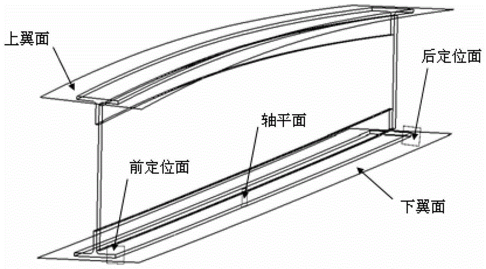
[0084] The focus of this embodiment relates to a parametric design method for level 1 components of aircraft beams, walls, and ribs: parametric components are used to express the beams, walls, and ribs in the aircraft structure, and aircraft beams, walls, and ribs are used. The parametric expression of level components specifically involves the following four parts: "basic attributes", "geometric attributes", "non-geometric attributes", and "two-dimensional cross-sectional views"; among them:
[0085] "Basic attributes" specifically include: component name, version number, creation time, component description, manufacturing proc...
example
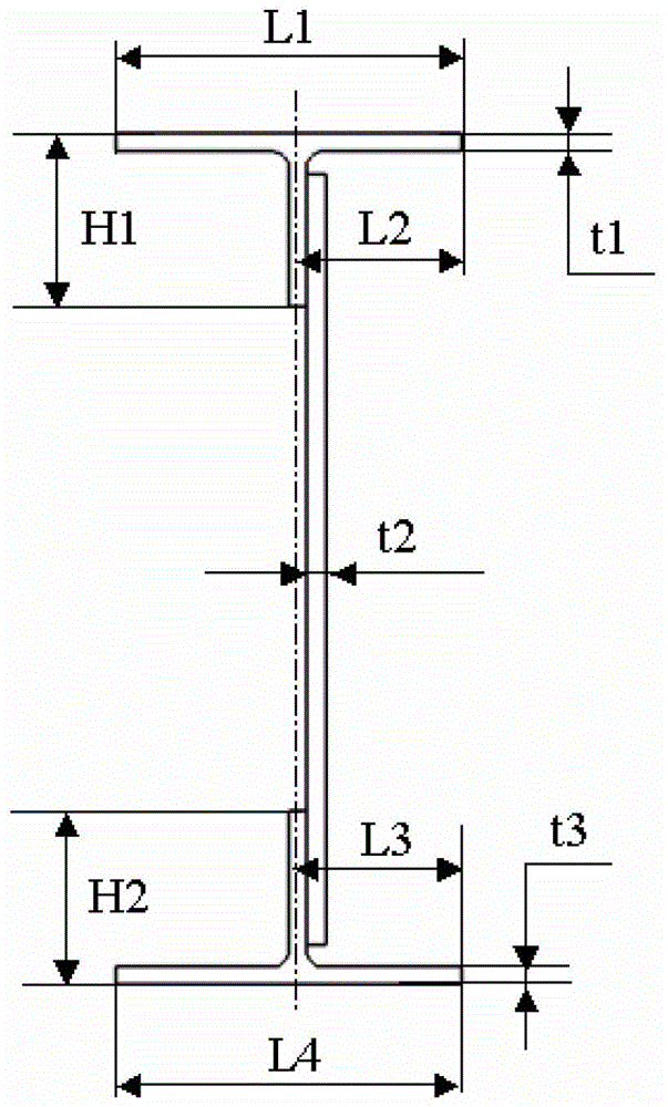
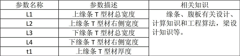
[0090] Example: For composite beam wall members whose upper and lower edge strips are T-shaped extruded profiles, they can be decomposed into upper and lower edge strips and webs. For the upper edge bar, the simplified unit and calculation attribute table are shown in Table 2.
[0091] Table 2 can be simplified to the calculation properties and correlation formulas of members of bar and beam elements
[0092]
[0093] For the lower edge bar, the simplified element and calculation attributes are the same as the upper edge bar, but the difference lies in the parameters of the correlation formula.
[0094] For webs, the simplified elements and calculation properties are shown in Table 3.
[0095] Table 3 can be simplified to the calculated properties of various types of plate elements
[0096]
[0097] "Two-dimensional cross-sectional view": Used to correctly understand the physical meaning of each parameter of the component when the component is instantiated.
[0098] The parametric desig...
PUM
Abstract
The invention discloses a parametrization design method of first-level member of beam, wall and rib type parts of airplane. The parametrization design method comprises the following steps of: stating the beam, wall and rib type parts in the airplane structure by using parametrization members, wherein the parametrization statement of the first-level members of the beam, wall and rib parts of the airplane specifically relates to contents of four parts as follows: 1) the basic attributes specifically comprise the names of the members, the version numbers, the establishment time, the member description, the manufacturing process and the remarks; 2) the geometric attributes specifically consist of two parts of positioning parameters and cross-section parameters; 3) non-geometric attributes specifically relate to decomposition schemes and non-geometric attribute information corresponding to the decomposition schemes; and 4) a two-dimensional sectional drawing is used for helping a user to correctly understand the physical meaning of the parameters of the members in member instantiation. The parametrization design method is helpful in establishing a member bank system, functional and performance model data basis for the standardization and simulation analysis in airplane design is provided, the coordination of data of a geometric model machine and a functional model machine / performance model machine is ensured, the design quality of the airplane is improved, and the research and manufacturing period is shortened.
Description
[0001] Technical field: [0002] The invention relates to the technical field of aircraft structure design, and in particular provides a parametric design method for level 1 components of aircraft beams, walls and ribs. [0003] Background technique: [0004] Among the existing technologies, with the continuous in-depth application of CAD technology, CAD technology has become an indispensable tool for aircraft design departments. The designer needs to solve the problem of determining the parameters before using CAD to complete the three-dimensional solid model of the product-design. If CAD technology cannot participate in the determination of product parameters, then the application of CAD technology in design is only the description of the design results, not the real design. The CAD system must participate in the product design process, and the model structure of the design process becomes the key. This model should be able to fit the data requirements of CAD / CAE and other system...
Claims
Application Information
Patent Timeline
Application Date:The date an application was filed.
Publication Date:The date a patent or application was officially published.
First Publication Date:The earliest publication date of a patent with the same application number.
Issue Date:Publication date of the patent grant document.
PCT Entry Date:The Entry date of PCT National Phase.
Estimated Expiry Date:The statutory expiry date of a patent right according to the Patent Law, and it is the longest term of protection that the patent right can achieve without the termination of the patent right due to other reasons(Term extension factor has been taken into account ).
Invalid Date:Actual expiry date is based on effective date or publication date of legal transaction data of invalid patent.
Patent Type & AuthorityPatents(China)
IPC IPC(8): G06F17/50
Inventor杨旭朴春雨吴斌
OwnerSHENYANG AIRCRAFT DESIGN INST AVIATION IND CORP OF CHINA

