Composite welding method combining laser with friction stir welding
A technology of friction stir welding and hybrid welding, applied in laser welding equipment, welding equipment, non-electric welding equipment and other directions, can solve the problems of low welding heat input, restricting the development of laser welding of stainless steel, and high requirements for mounting accuracy, and achieves good results. The effect of welding
- Summary
- Abstract
- Description
- Claims
- Application Information
AI Technical Summary
Problems solved by technology
Method used
Image

Examples
Embodiment 1
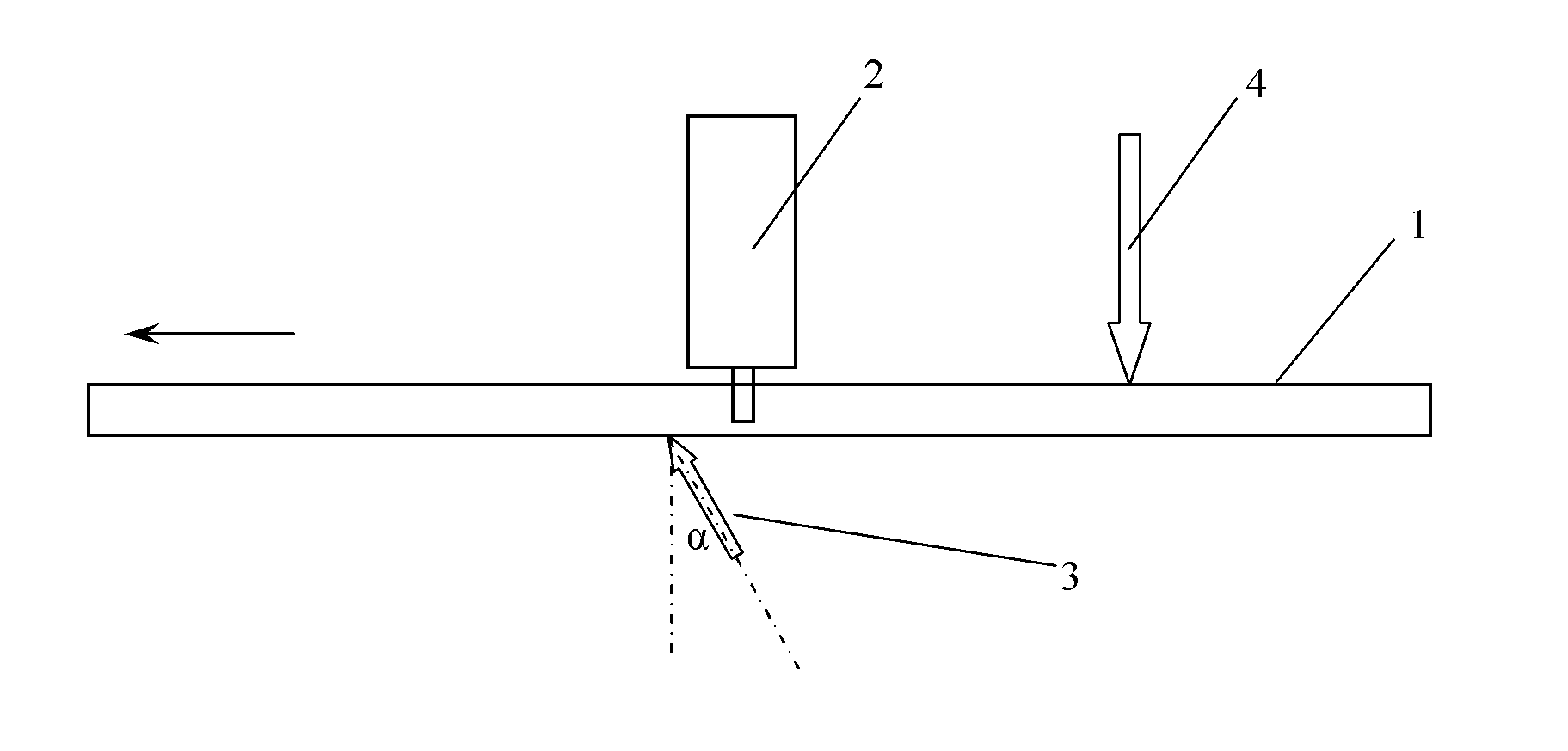
[0012] The thickness of the stainless steel plate 1 to be welded is 20mm, and the first laser beam 3, the friction stirring head 2, and the second laser beam 4 are arranged in sequence along the welding direction; the first laser beam 3 originates from a CO2 laser, and the first laser beam The angle between the central line of 3 and the vertical direction on the surface of the stainless steel plate is α=30°, the laser power of the first laser beam is P1=1400w, adjust the position of the focus of the laser beam relative to the surface of the stainless steel plate to be welded, so that The diameter of the laser spot radiated on the workpiece to be welded is at 5mm; the second laser beam 4 originates from a CO2 laser, the center line of the second laser beam is perpendicular to the surface of the stainless steel plate, and the first laser beam's Laser power is P2=2000w; The included angle between the center line of the friction stirring head and the vertical direction on the surfa...
Embodiment 2
[0014] The thickness of the stainless steel plate 1 to be welded is 25mm, and the first laser beam 3, the friction stirring head 2, and the second laser beam 4 are arranged in sequence along the welding direction; the first laser beam 3 originates from a CO2 laser, and the first laser beam The angle between the central line of 3 and the vertical direction on the surface of the stainless steel plate is α=30 °, the laser power of the first laser beam is P1=1800w, adjust the position of the focus of the laser beam relative to the surface of the stainless steel plate to be welded, so that The diameter of the laser spot radiated on the workpiece to be welded is at 3mm; the second laser beam 4 originates from a CO2 laser, the center line of the second laser beam is perpendicular to the surface of the stainless steel plate, and the first laser beam's The laser power is P2=4000w; The center line of the friction stirring head and the vertical angle of the stainless steel plate surface a...
Embodiment 3
[0016] The thickness of the stainless steel plate 1 to be welded is 35mm, and the first laser beam 3, the friction stirring head 2, and the second laser beam 4 are arranged successively along the welding direction; the first laser beam 3 originates from a CO2 laser, and the first laser beam The angle between the central line of 3 and the vertical direction on the surface of the stainless steel plate is α=15°, the laser power of the first laser beam is P1=2000w, adjust the position of the focus of the laser beam relative to the surface of the stainless steel plate to be welded, so that The diameter of the laser spot radiated on the workpiece to be welded is at 4mm; the second laser beam 4 originates from a CO2 laser, the center line of the second laser beam is perpendicular to the surface of the stainless steel plate, and the first laser beam's Laser power is P2=3500w; The included angle between the center line of the friction stirring head and the vertical direction on the surf...
PUM
| Property | Measurement | Unit |
|---|---|---|
| thickness | aaaaa | aaaaa |
| diameter | aaaaa | aaaaa |
| thickness | aaaaa | aaaaa |
Abstract
Description
Claims
Application Information