Lighting apparatus

A technology for lighting appliances and appliances, which is applied to lighting devices, fixed lighting devices, lighting and heating equipment, etc., and can solve the problems of darkening of the outer edge, light spots, and difficulty reaching the main body of the appliance, so as to reduce the light spots and ensure the amount of irradiated light Effect

Active Publication Date: 2015-06-17
PANASONIC CORP
View PDF9 Cites 0 Cited by
  • Summary
  • Abstract
  • Description
  • Claims
  • Application Information

AI Technical Summary

Problems solved by technology

[0004] In the lighting fixture described in the above-mentioned Patent Document 1, the light from the LED is reflected by the reflector to increase the amount of light irradiated downward. However, it is difficult for the light from the LED to reach the outer edge of the fixture body. As a result, there are The problem that the above-mentioned outer edge part will become dark and cause light spots

Method used


Image

  • Lighting apparatus
  • Lighting apparatus
  • Lighting apparatus

Examples


Embodiment Construction

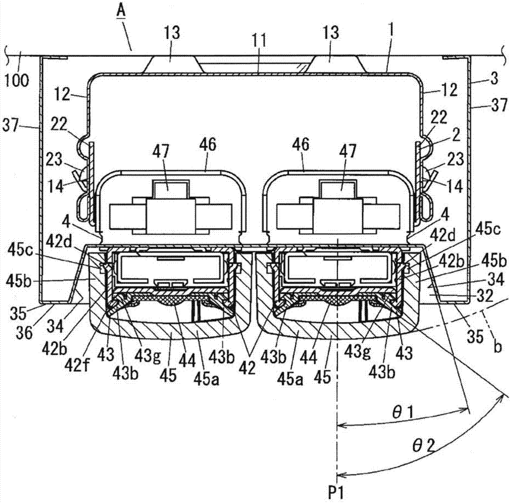
[0014] Below, based on Figure 1 to Figure 5 Embodiments of lighting fixtures will be described. The same code|symbol is attached|subjected to the same or similar part in the whole drawing, and description is abbreviate|omitted. The lighting fixture A of this embodiment is, for example, figure 1 As shown, it is attached to the ceiling surface (building surface) 100, and is used for illuminating the room which is a lighting space.

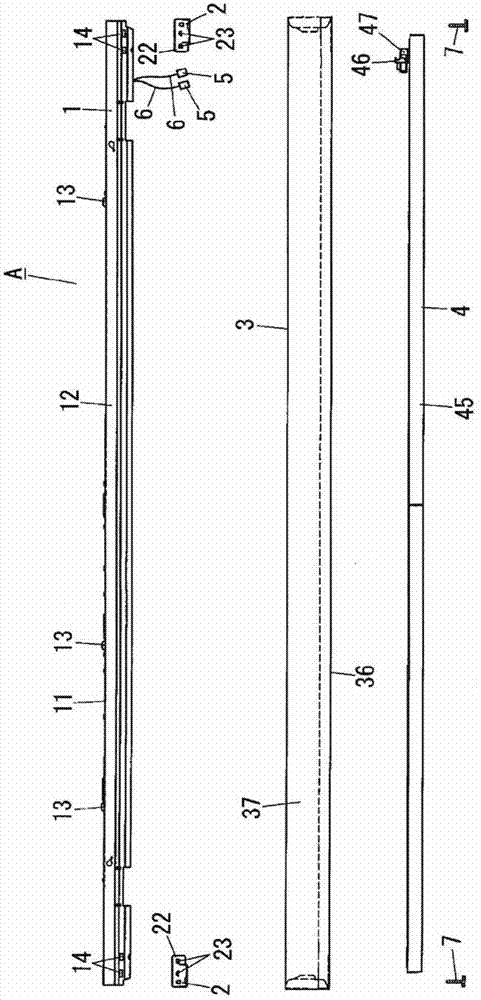
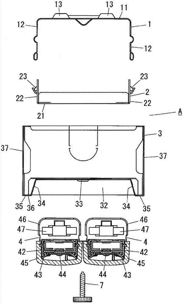
[0015] figure 1 It is a cross-sectional view along the longitudinal direction of a lighting fixture A according to the present embodiment. The lighting fixture A mainly includes a fixture main body 1 , a mounting bracket 2 , a front cover 3 , and a light source unit 4 .

[0016] Such as Figure 1 ~ Figure 3 As shown, the appliance main body 1 is formed into a U-shape in cross-sectional view by a long and rectangular plate-shaped bottom portion 11 and a side wall portion 12, and the side wall portion 12 extends from the width direction of the bot...


PUM


Abstract

A lighting apparatus (A) includes: an apparatus main body (1); a front cover (3) arranged before the apparatus main body (1), and a light source unit (4) arranged before the front cover (3). The front cover (3) is formed into a rectangular box with an opening on the rear side, and the front surface of the front cover (3) is provided with a housing concave part (32) for housing the light source unit (4) and a flat surface (35) horizontally extending from the opening end edge of the housing concave part (32). The light source unit (4) comprises a light source part (44), and a cover (45) for covering the light source part (44). The cover (45) is formed by a curved surface with a prescribed curvature, and has a bottom part (45a) arranged before the light source part (44). Moreover, at the state of mounting the lighting apparatus (A) on a ceiling surface (100), the flat surface (35) is arranged on one side near to the ceiling surface (100) relative to the extending curved surface (b) along the bottom part (45a) of the cover (45).

Description

technical field [0001] The present invention relates to lighting fixtures. Background technique [0002] Conventionally, there has been provided a lighting fixture that is attached to a ceiling to illuminate a room (for example, refer to Patent Document 1). This lighting fixture includes: a rectangular box-shaped fixture main body with an opening on its lower surface; a plurality of LED lamps each equipped with a plurality of LEDs arranged horizontally in the fixture main body at predetermined intervals; and a plurality of reflectors arranged on each Between adjacent LED lamps, the light from the LEDs is reflected downward. In this lighting fixture, part of the light radiated from the LED is directly irradiated downward, and the remaining light is reflected by the reflector to be irradiated downward. Therefore, the amount of downward irradiated light can be increased by the amount of reflected light. [0003] Patent Document 1: Japanese Utility Model Registration No. 31475...

Claims


Application Information

Patent Timeline
Patent Type & Authority Patents(China)
IPC IPC(8): F21S8/04F21V7/00F21V13/04F21Y101/02
Inventor 宫原荣二溝谷彻秋田宽齐藤优子今安一哉村上久典
Owner PANASONIC CORP
Why Eureka
Try Eureka