
Lamp for vehicles and vehicle

A vehicle lamp and lens technology, which is applied in the direction of headlights, road vehicles, vehicle parts, etc., can solve the problem that it is difficult to achieve high uniformity, achieve high uniformity, and suppress glare

Active Publication Date: 2019-03-05
ZKW GRP GMBH
View PDF11 Cites 0 Cited by
  • Summary
  • Abstract
  • Description
  • Claims
  • Application Information

AI Technical Summary

Problems solved by technology

[0006] According to the prior art LED or LD, there is a problem that it is difficult to realize a lamp with high uniformity

Method used


Image

  • Lamp for vehicles and vehicle
  • Lamp for vehicles and vehicle
  • Lamp for vehicles and vehicle

Examples


Embodiment Construction

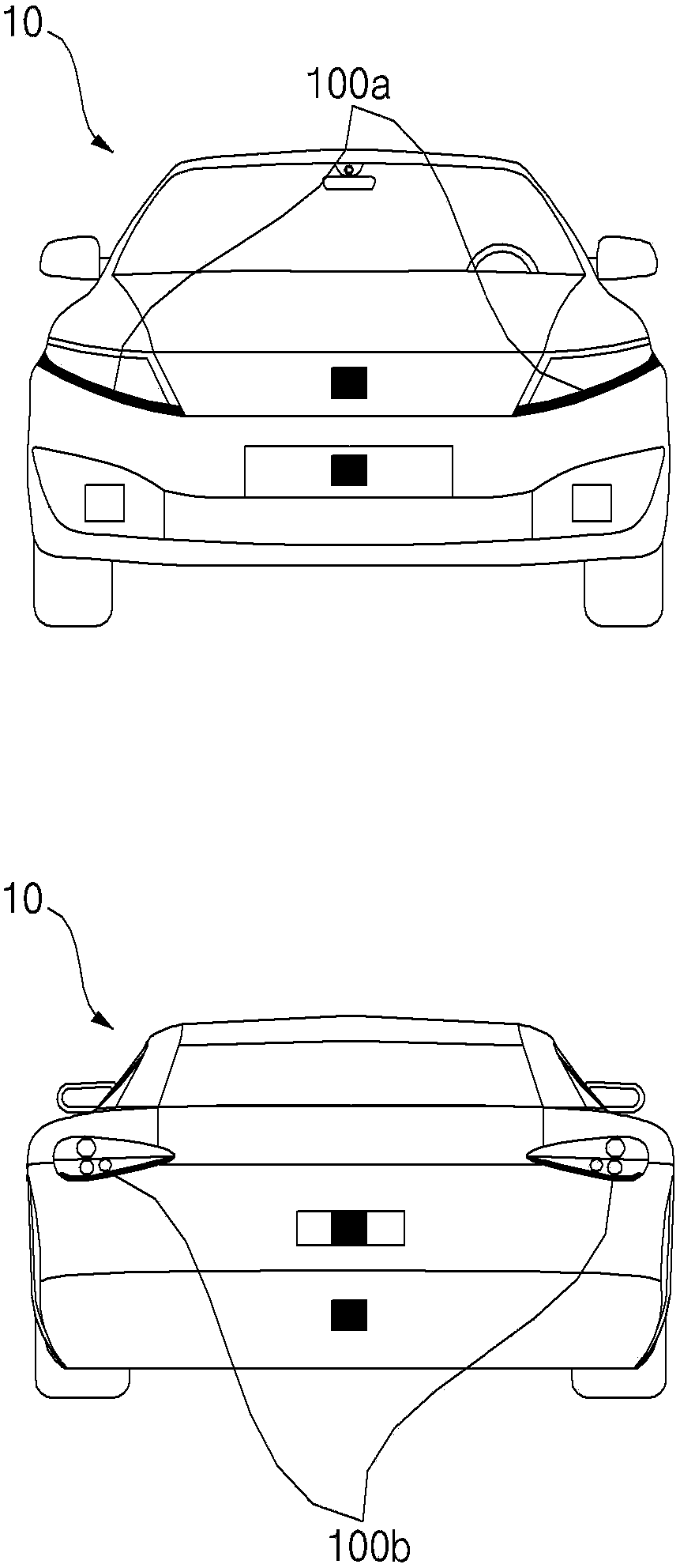
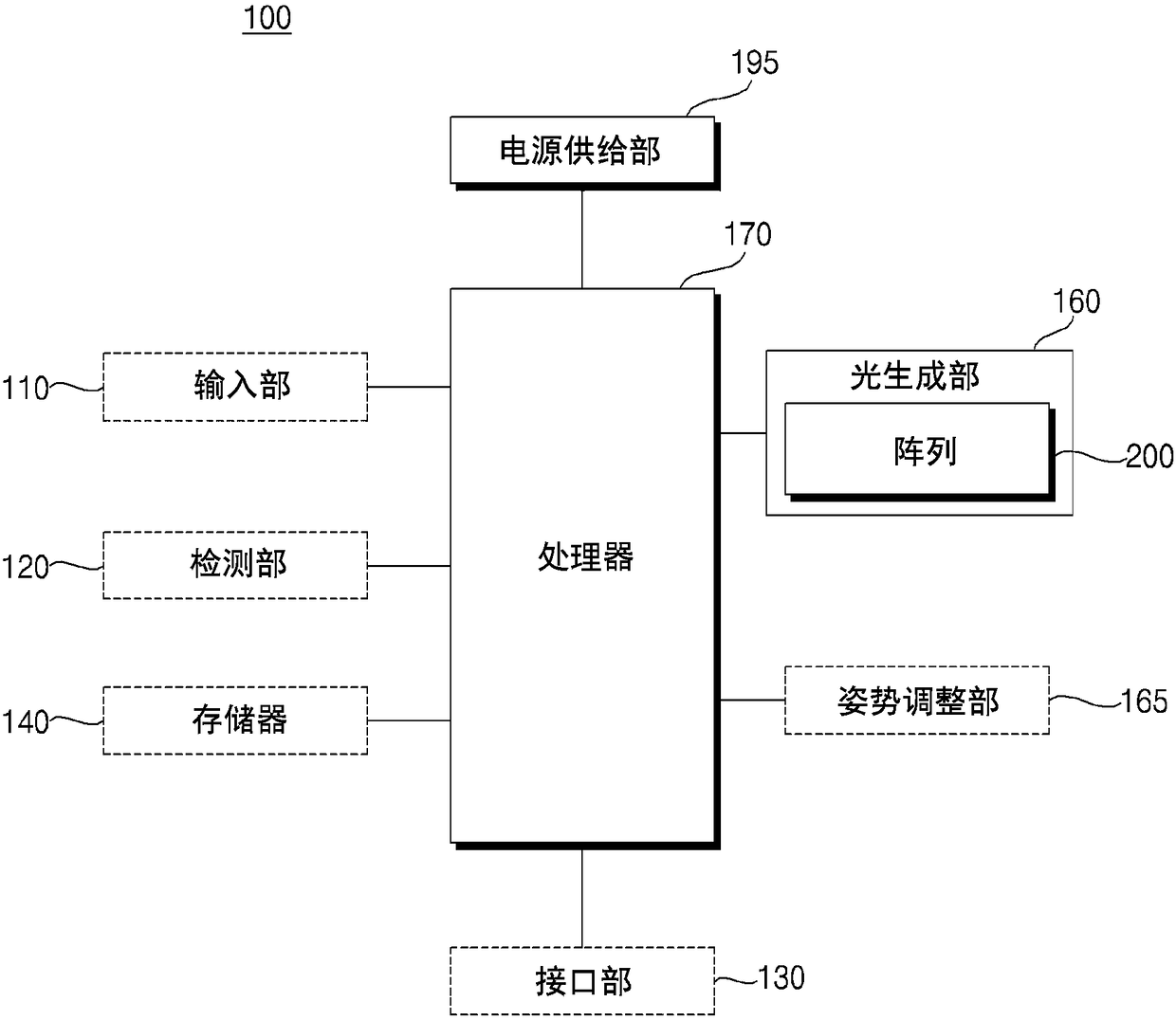
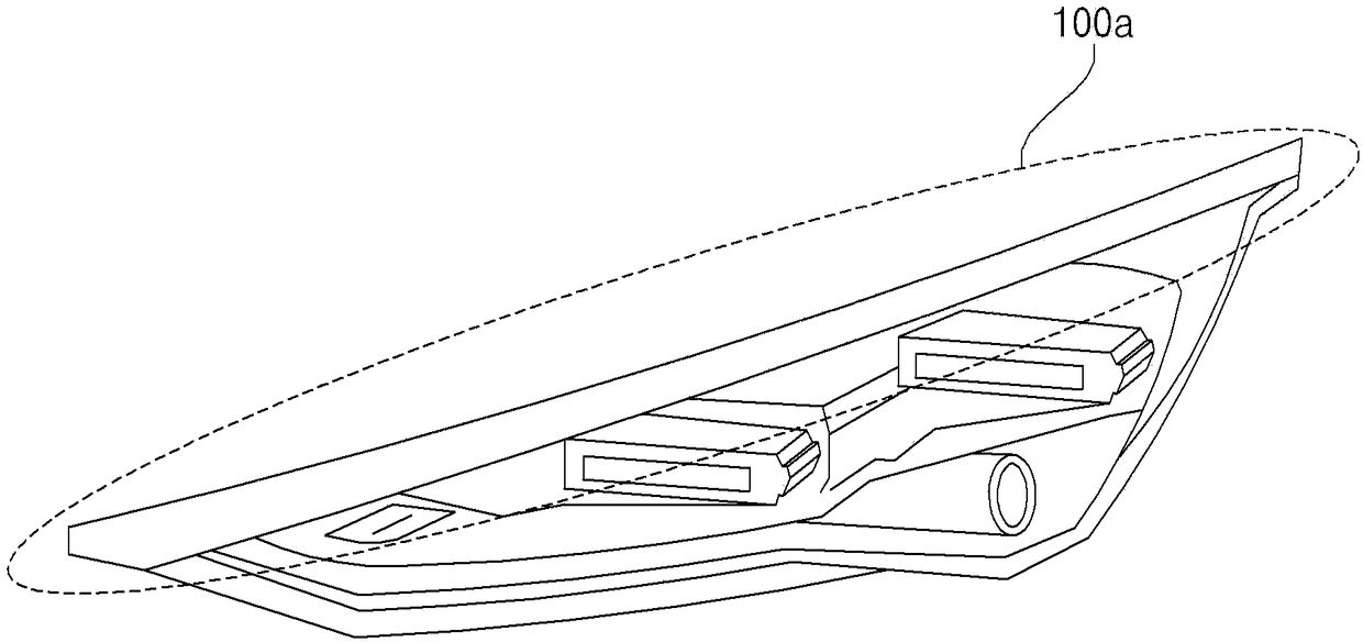
[0041] Hereinafter, the embodiments disclosed in this specification will be described in detail with reference to the accompanying drawings. Regardless of the reference numerals, the same or similar structural elements are denoted by the same reference numerals, and repeated descriptions of these are omitted. The suffixes "module" and "part" of the structural elements used in the following description are only given or mixed in consideration of facilitating the writing of the specification, and they do not have different meanings or functions. In addition, in the process of describing the embodiment disclosed in this specification, if it is determined that the specific description of the related known technology will obscure the gist of the embodiment disclosed in this specification, the detailed description will be omitted. It should be understood that the drawings are only to facilitate the understanding of the embodiments disclosed in this specification, and the technical ide...


PUM


Abstract

Implementations disclosed herein enable a lamp for a vehicle that is comprising: a light generation unit comprising an array provided with a plurality of micro-light emitting diode (micro-LED) chips arranged therein; and a lens configured to redirect light beams generated by the light generation unit, wherein the light generation unit is configured to output a plurality of beams having a divergence angle defined in a vertical direction, and wherein the lens is arranged to have a largest vertical cross-section thereof inscribed in the divergence angle of the beams that are output from the lightgeneration unit.

Description

Technical field [0001] The invention relates to a vehicle lamp and a vehicle. Background technique [0002] A vehicle is a device that moves in a direction desired by a user riding in it. As a representative, a car can be cited. [0003] Various lights are installed in the vehicle. For example, a head lamp, a rear combination lamp (rear combination lamp), a daytime running signal lamp (DRL: daytime running l amp), and a fog lamp (foglamp) are installed in the vehicle. [0004] As the light source of various lamps installed in a vehicle, various elements can be used. [0005] On the other hand, the light output from daytime driving lights, tail lamps, and stop lamps needs to maintain an appropriate amount of light and have high uniformity. [0006] According to the LED or LD of the related art, there is a problem that it is difficult to realize a lamp with high uniformity. Summary of the invention [0007] In order to solve the above-mentioned problems, an object of the embodiments of...

Claims


Application Information

Patent Timeline
Patent Type & Authority Applications(China)
IPC IPC(8): F21S41/141F21S41/25F21S43/14F21S43/20F21W107/10F21Y115/10
CPCF21S41/25F21S43/20F21S43/14F21S41/141F21Y2115/10F21W2107/10F21S41/143F21S41/147F21S41/255F21S41/26F21S41/153F21S43/26F21S41/20F21W2102/00F21W2103/35F21W2103/55
Inventor 赵胄雄赵汉奎
Owner ZKW GRP GMBH
Learn More