Camera device and flickering detecting method for camera device

A camera device and flicker detection technology, applied in image communication, parts of color TV, parts of TV system, etc.

Active Publication Date: 2013-04-17
OM DIGITAL SOLUTIONS CORP
View PDF6 Cites 39 Cited by
  • Summary
  • Abstract
  • Description
  • Claims
  • Application Information

AI Technical Summary

Problems solved by technology

[0027] However, the luminance fluctuations caused by the movement and shake of the subject are superimposed on the imaging output, so there is a technical problem as follows: when the fl

Method used


Image

  • Camera device and flickering detecting method for camera device
  • Camera device and flickering detecting method for camera device
  • Camera device and flickering detecting method for camera device

Examples


Embodiment Construction

[0066] Embodiments of the present invention will be described in detail below with reference to the accompanying drawings.

[0067] image 3 It is a block diagram showing a configuration example of a camera realizing an imaging device according to an embodiment of the present invention. In this embodiment, an example of application to a digital single-lens reflex camera will be described as an example of a camera.

[0068] Such as image 3 As shown, the digital single-lens reflex camera (hereinafter simply referred to as “camera”) includes a main body unit 100 , for example, an interchangeable lens unit (ie, lens barrel) 200 , and a recording medium 131 on which image data obtained by shooting is recorded.

[0069] Wherein, the recording medium 131 is connected to the main unit 100 through the communication connector 130 .

[0070] The lens unit 200 is freely detachable by means of an unillustrated lens mounter provided on the front surface of the main unit 100 , and the le...


PUM


Abstract

The invention provides a camera device and a flickering detecting method for the camera device. Under a condition that the frame rate and the frequency of the flickering light source are synchronous, high-precision flickering detection can be realized. A camera element having an electronic shutter function is enabled to take shooting actions in a predetermined period. Whether flickering element is contained in light of a shot object or not is detected according to camera output obtained the camera outputs obtained in different integral time and in same integral time at different time points.

Description

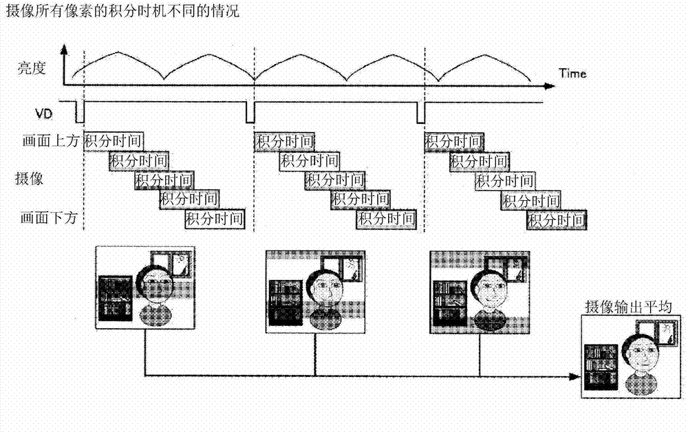
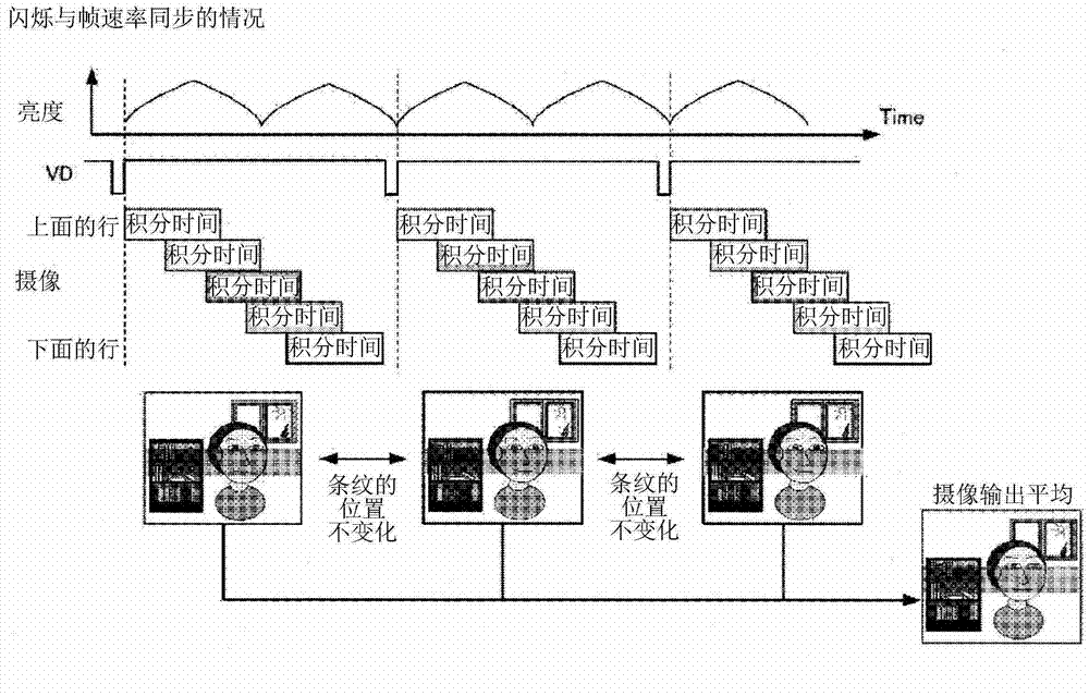
technical field [0001] The invention relates to an imaging device and a flicker detection method of the imaging device. Background technique [0002] When an imaging device is used to capture an image of a subject irradiated by repeatedly flickering illumination, generally called a flickering light source, it is a technical problem that brightness differences in images obtained by the imaging device occur depending on exposure timing. [0003] As a method of detecting this scintillation component, techniques disclosed in the following Patent Document 1, Patent Document 2, Patent Document 3, and the like are known. The prior art in these Patent Documents 1 to 3 is a technique of obtaining an image in which the influence of the flicker component is reduced by averaging a predetermined number of continuous multi-frame imaging outputs when photographing with an integration time shorter than the flicker cycle. data. [0004] In addition, Patent Document 4 discloses a technique ...

Claims


Application Information

Patent Timeline
IPC IPC(8): H04N5/235H04N5/232
Inventor 工藤泰则
Owner OM DIGITAL SOLUTIONS CORP
Why Eureka
Try Eureka