
Image sensor, electronic apparatus, and driving method of electronic apparatus

a technology of electronic equipment and image sensor, which is applied in the direction of color television details, television system details, television systems, etc., can solve the problem of difficult reading at high-speed frame rate, and achieve the effect of simple configuration

Active Publication Date: 2008-11-20
SONY SEMICON SOLUTIONS CORP
View PDF10 Cites 41 Cited by
  • Summary
  • Abstract
  • Description
  • Claims
  • Application Information

AI Technical Summary

Benefits of technology

[0026]In the present invention, it is possible to obtain a high-quality image with a simple configuration.

Problems solved by technology

As a result, reading at a high-speed frame rate becomes difficult.

Method used


Image

  • Image sensor, electronic apparatus, and driving method of electronic apparatus
  • Image sensor, electronic apparatus, and driving method of electronic apparatus
  • Image sensor, electronic apparatus, and driving method of electronic apparatus

Examples


Embodiment Construction

[0040]Hereinafter, embodiments of the present invention will be described. The correspondence relationship between configuration requirements of the present invention and embodiments described in this specification or drawings is as follows. This description is made to confirm that embodiments supporting the present invention are described in this specification or drawings. Therefore, even if there exists an embodiment that is described in this specification or drawings but not described herein as what corresponds to the configuration requirements of the present invention, the embodiment is not to be interpreted as an embodiment which does not correspond to the configuration requirements. In contrast, even if an embodiment is described herein as what corresponds to the configuration requirements, the embodiment is not to be interpreted as an embodiment which does not correspond to a configuration requirement other than the configuration requirements.

[0041]An image sensor according t...


PUM


Abstract

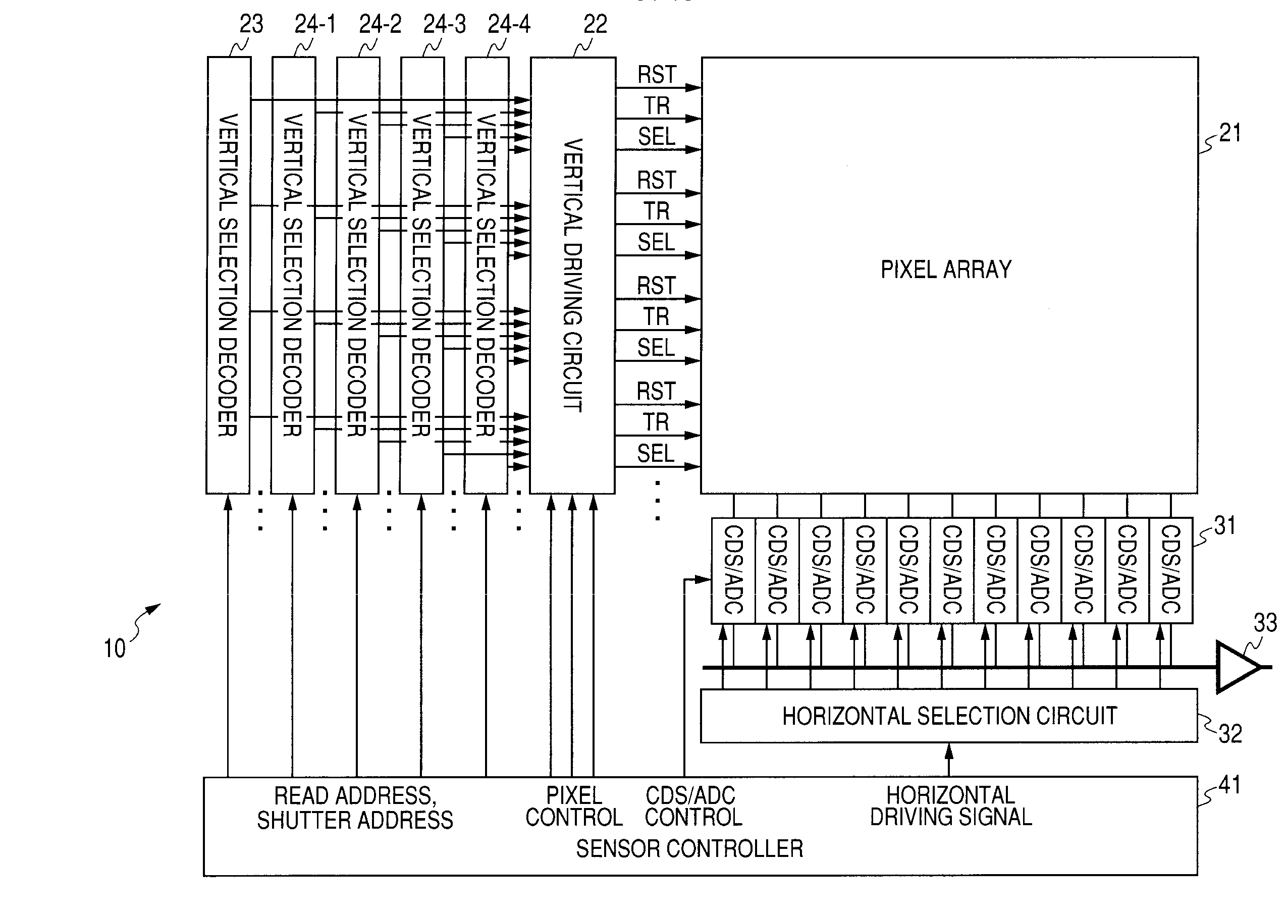
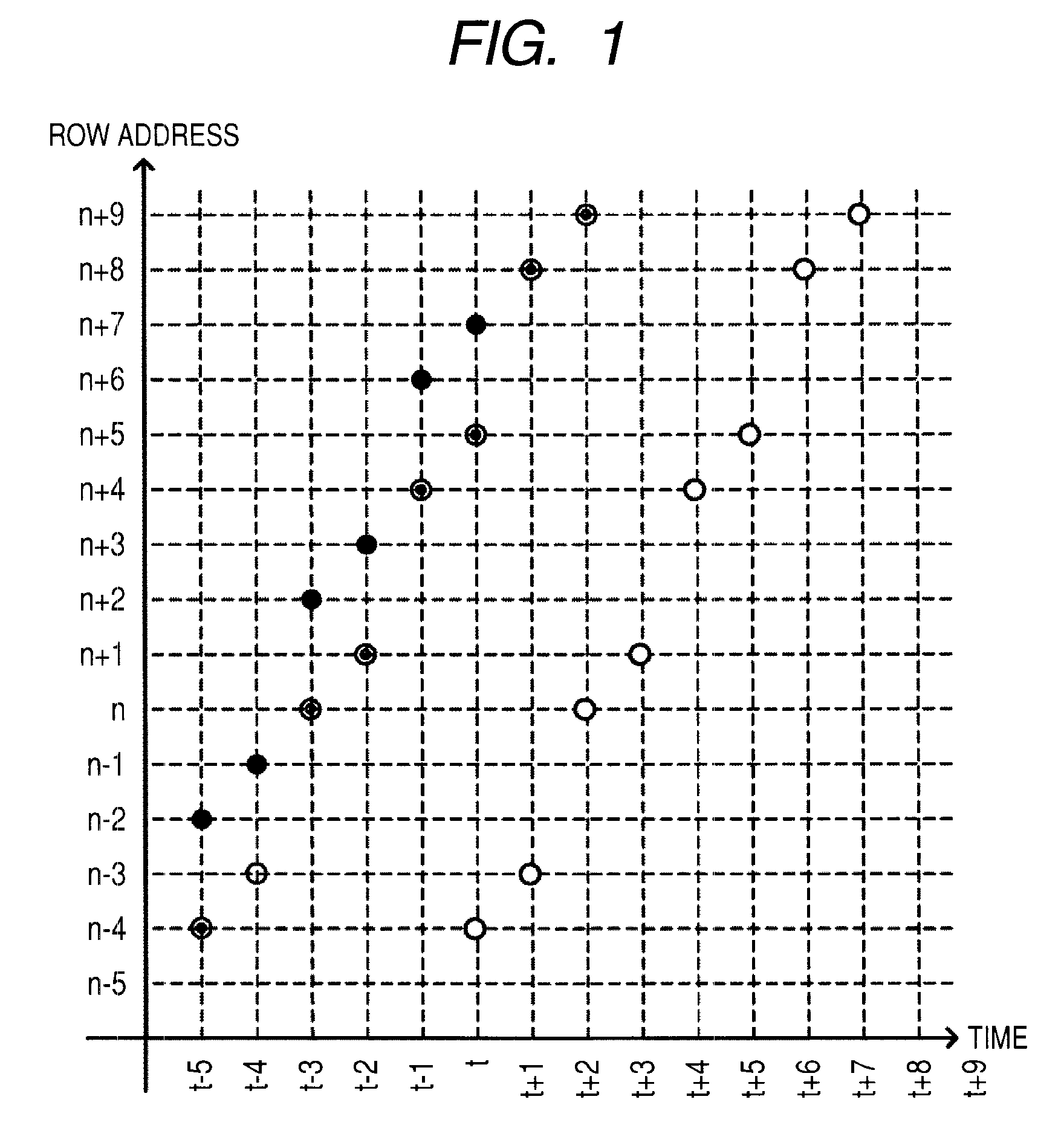
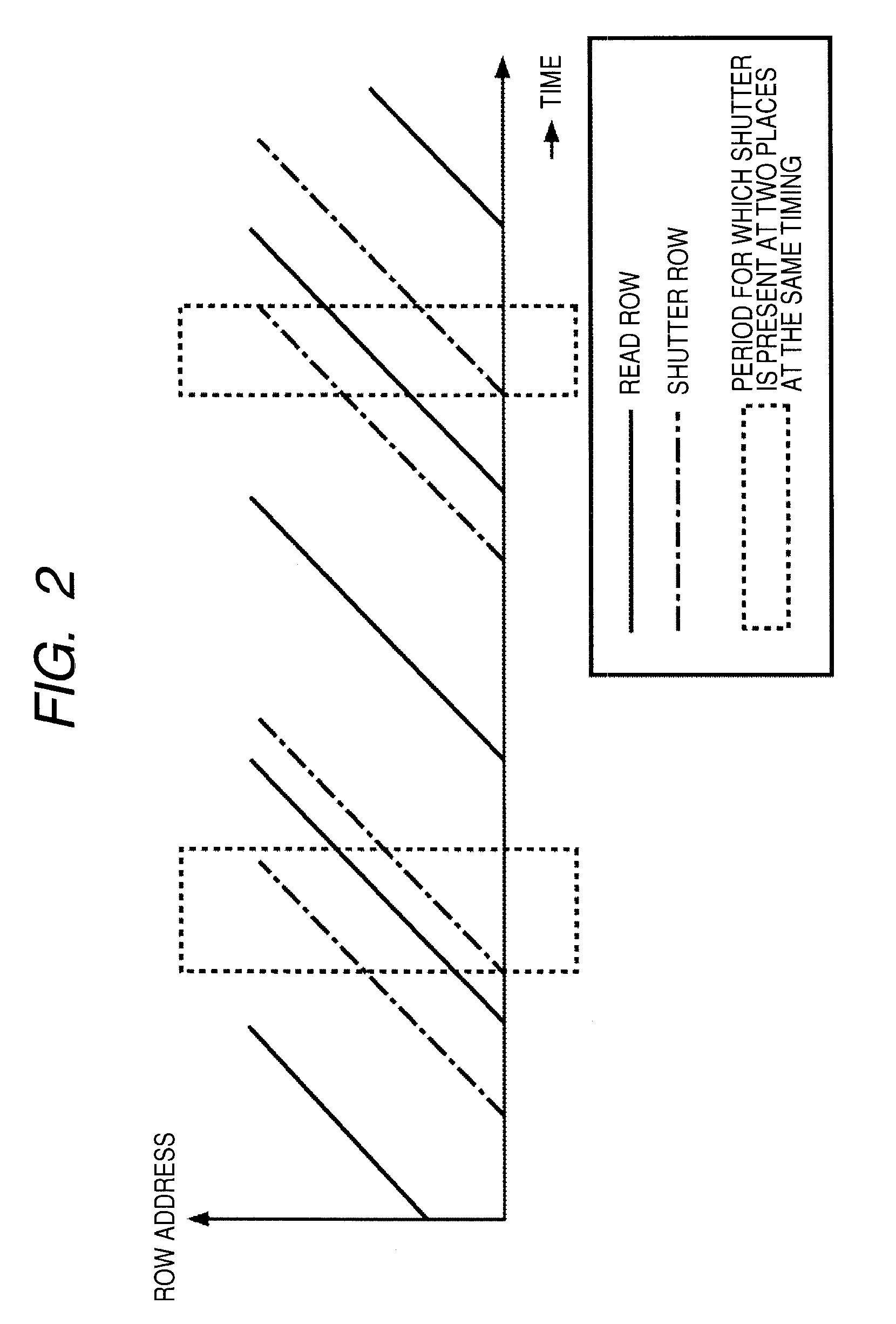
An image sensor that supplies a control signal together with an address specifying each of a plurality of pixels arrayed in a pixel array with predetermined rows and columns to thereby perform an electronic shutter operation on a pixel corresponding to the address or perform reading of a pixel signal of a pixel corresponding to the address, is disclosed. The sensor includes: address generating means for generating a shutter row address specifying a row of pixels, on which an electronic shutter operation is to be performed within one horizontal period, among the pixels arrayed in the pixel array and a read row address specifying a row of pixels on which reading of a pixel signal is to be performed within the same one horizontal period; first storage means for storing the shutter row address; and second storage means for storing the read row address.

Description

CROSS REFERENCES TO RELATED APPLICATIONS[0001]The present invention contains subject matter related to Japanese Patent Application JP 2007-132096 filed in the Japanese Patent Office on May 17, 2007, the entire contents of which being incorporated herein by reference.BACKGROUND OF THE INVENTION[0002]1. Field of the Invention[0003]The present invention relates to an image sensor, an electronic apparatus, and a driving method of an electronic apparatus, and more particularly, to an image sensor, an electronic apparatus, and a driving method of an electronic apparatus capable of obtaining a high-quality image with a simple configuration.[0004]2. Description of the Related Art[0005]A CMOS (complementary metal oxide semiconductor) image sensor and the like amplify signal charges accumulated in a photodiode, which is a photoelectric conversion element, with an active element and read the amplified signal charges as image information.[0006]In an X-Y address type solid-state imaging device, ...

Claims


Application Information

Patent Timeline
Patent Type & Authority Applications(United States)
IPC IPC(8): H04N5/76H04N5/335H04N25/00
CPCH04N3/155H04N3/1562H04N5/3591H04N5/341H04N5/3456H04N3/1568H04N25/40H04N25/441H04N25/445H04N25/531H04N25/533H04N25/621H04N25/7795H04N25/779H04N25/76H04N25/745
Inventor MAKINO, EIJI
Owner SONY SEMICON SOLUTIONS CORP
Learn More