AI technical title is built by Patsnap AI team. It summarizes the technical point description of the patent document.
A technology of imaging components and imaging devices, which is applied in the direction of electrical components, image communication, color TV components, etc., and can solve problems such as loss of grayscale in high-brightness areas and inability to reproduce colors faithfully
Inactive Publication Date: 2007-11-14
SEIKO EPSON CORP
View PDF1 Cites 40 Cited by
Summary
Abstract
Description
Claims
Application Information
AI Technical Summary
This helps you quickly interpret patents by identifying the three key elements:
Problems solved by technology
Method used
Benefits of technology
Problems solved by technology
Moreover, since the joint method performs level compression on high-brightness areas, in devices capable of displaying a wide dynamic range (for example, devices capable of displaying a contrast ratio of 10000:1, etc.), the grayscale of high-brightness areas will be damaged. , and the fact that colors cannot be reproduced faithfully (in the case of a sensor with a color filter attached) due to linearity disappearance
Method used
Image
Click on the blue label to locate the original text in one second.
Reading with bidirectional positioning of images and text.
Examples
no. 1 Embodiment approach
[0097] Next, a first embodiment of the imaging element, imaging device, imaging system, and imaging method of the present invention will be described with reference to the drawings. 1 to 13 are diagrams showing a first embodiment of an imaging element, an imaging device, an imaging system, and an imaging method of the present invention.
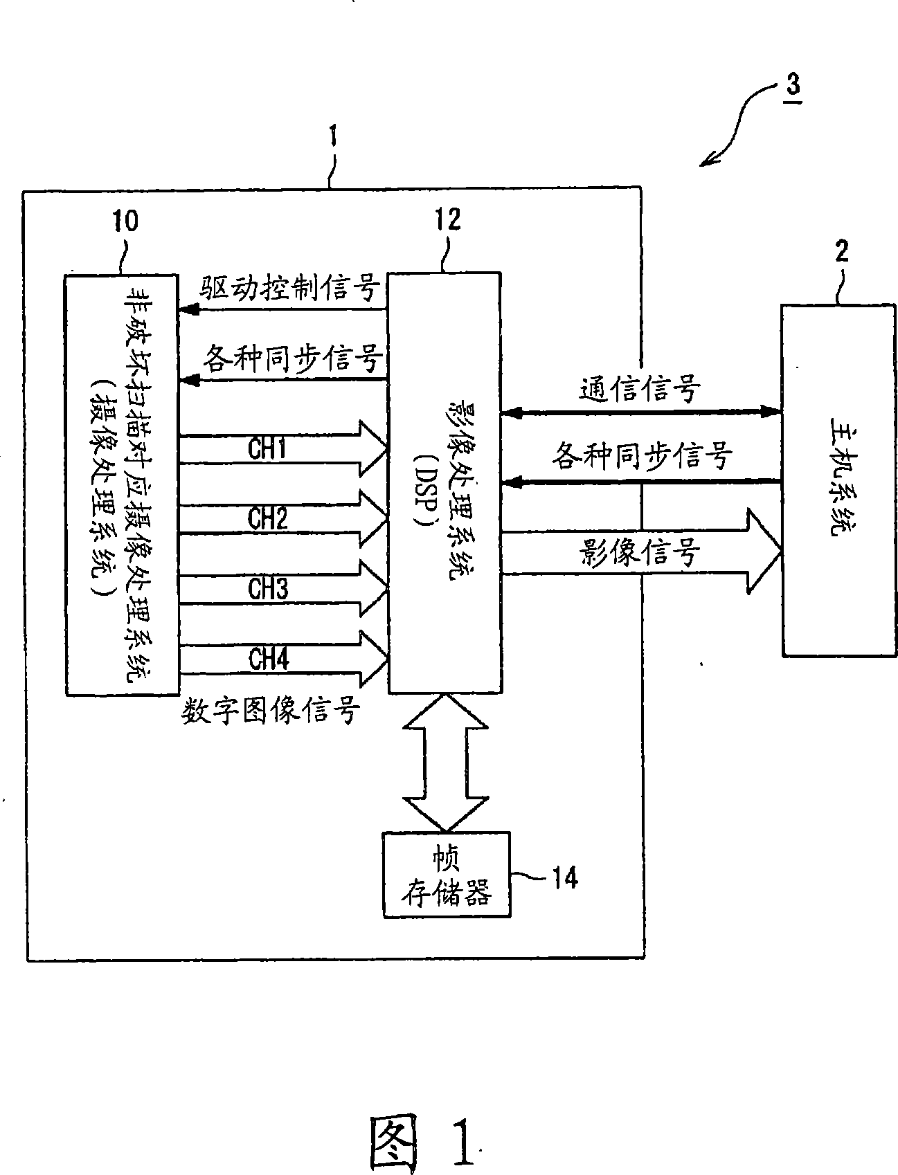
[0098] Next, a schematic configuration of the imaging device 1 of the present invention will be described with reference to FIG. 1 . Here, FIG. 1 is a block diagram showing a schematic configuration of an imaging system 3 of the present invention.
[0099] As shown in FIG. 1 , the imaging system 3 is configured to include an imaging device 1 and a host system 2 .
[0100] The imaging device 1 is configured to include an imaging processing system 10 corresponding to non-destructive scanning (hereinafter referred to as imaging processing system 10 ), which reads the image from the sensor in a destructive reading method during the exposure peri...
no. 2 Embodiment approach
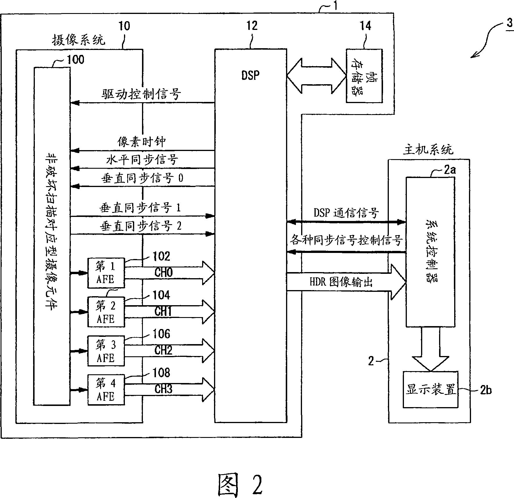
[0212] Next, a second embodiment of the imaging device, imaging device, imaging system, and imaging method of the present invention will be described with reference to the drawings. 14 is a diagram showing a second embodiment of the imaging device, imaging device, imaging system, and imaging method of the present invention.
[0213] In this embodiment, both ultra-short exposure pixel data and short exposure pixel data are obtained as non-standard pixel data, saturation / unsaturation prediction is performed based on the ultra-short exposure pixel data and short exposure pixel data, and the target pixel is predicted to be in the short In the case of saturation at exposure time T1, composite output (HDR pixel data) is generated using all ultra-short-exposure pixel data, short-exposure pixel data, and standard-exposure pixel data subjected to differential processing from the reference image data, which is the same as The first embodiment described above is different. Therefore, th...
PUM
Abstract
An image pickup device having a photoelectric conversion unit having a plurality of photoelectric conversion elements arranged in a matrix pattern for converting exposed light into electric charges and accumulating the same and an electronic shutter function for controlling the exposure time for each frame including: a first reader for reading out electric charges exposed during a standard exposure time from respective pixels including the photoelectric conversion elements in the exposed area of the photoelectric conversion unit in a destructive read-out method; a second reader for reading out electric charges exposed during a short exposure time, which is an exposure time shorter than the standard exposure time, from the respective pixels including the photoelectric conversion elements during the same exposure period as the first reader in a nondestructive read-out method; and a saturation predictor for predicting whether or not the amounts of accumulated electric charges in the respective pixels being exposed during the standard exposure time are saturated on the basis of a non-standard exposure pixel data including the electric charges being exposed during the short exposure time, which are read out by the second reader.
Description
technical field [0001] The present invention relates to an imaging element and an imaging device capable of reading charges from a photoelectric conversion element using a destructive reading method and a nondestructive reading method. Background technique [0002] One of the problems of an imaging device using a solid-state imaging device represented by a digital camera is a problem of a narrow dynamic range. Therefore, white flashes (白とび) (saturation of pixels) in high-brightness areas and dark spots (tsuぶれ) in low-brightness areas occur in images obtained by shooting scenes with very high contrast. [0003] Currently, various methods have been proposed in order to solve the above-mentioned problems. As one of them, there is a method of synthesizing two (or more) images with different exposure amounts, and known examples using this method include, for example, the imaging device described in Patent Document 1, and the like. [0004] This imaging device is an imaging dev...
Claims
Application Information
Patent Timeline
Application Date:The date an application was filed.
Publication Date:The date a patent or application was officially published.
First Publication Date:The earliest publication date of a patent with the same application number.
Issue Date:Publication date of the patent grant document.
PCT Entry Date:The Entry date of PCT National Phase.
Estimated Expiry Date:The statutory expiry date of a patent right according to the Patent Law, and it is the longest term of protection that the patent right can achieve without the termination of the patent right due to other reasons(Term extension factor has been taken into account ).
Invalid Date:Actual expiry date is based on effective date or publication date of legal transaction data of invalid patent.

