Imaging apparatus with shake correction

a technology of shake correction and imaging apparatus, which is applied in the field of imaging apparatus, can solve the problems of significant influence of shake correction, deterioration of camera shake correction performance, and generation of impact vibration, and achieve the effect of high shake correction accuracy and suppression of exposure unevenness resulting from a difference in curtain speed between the front curtain and the rear curtain

Active Publication Date: 2012-09-04
SONY CORP
View PDF26 Cites 39 Cited by
  • Summary
  • Abstract
  • Description
  • Claims
  • Application Information

AI Technical Summary

Benefits of technology

[0009]According to this configuration, at the time of shooting, the control means executes an electronic shutter control (exposure starting operation by an electronic focal plane shutter) for starting exposure on the imaging device by means of a reset signal supplied to each of the pixels from the timing signal generating means. Therefore, the correction drive means can perform a shake correction drive without being subject to the influence of vibration due to travel of the front curtain of the mechanical focal plane shutter.
[0031]According to the invention as set forth in Claim 8, in the imaging apparatus in which the imaging device and the mechanical focal plane shutter are integrally subjected to a shake correction drive by the correction drive means, the misoperation suppressing effect in the shake correction drive becomes more pronounced, thereby making it possible to realize high precision of shake correction even with the imaging apparatus configured as described above.

Problems solved by technology

However, a problem that often occurs with this kind of imaging apparatus incorporating a camera shake correction function is that the camera shake correction performance deteriorates due to vibrations generated by the traveling curtains of the mechanical focal plane shutter.
When the curtains travel so as to open the optical path and the opening of the optical path is completed, the curtains collide against each other within the shutter unit, generating impact vibration (shutter stopping vibration).
Because this impact vibration affects a camera shake correction drive mechanism situated in close proximity, that is, because a force different from that for camera shake correction is applied to the camera shake correction drive mechanism due to the impact vibration, a displacement from a predetermined correction position occurs, causing misoperation.
In particular, since no fixation by locking or static friction is performed during the shake correction drive, the influence of this problem becomes significant.
However, since controlling the speed of curtains requires a rather complex mechanism, this involves the problem of hindering downsizing of the imaging apparatus and driving up cost.
Although the above-mentioned problem of impact vibration can be overcome by applying the technique disclosed in Japanese Unexamined Patent Application Publication No. 2000-152057 so that the front curtain is always effected by an electronic focal plane shutter, this brings about another problem of exposure unevenness resulting from the fact that the front curtain is effected by an electronic focal plane shutter and the rear curtain is effected by a mechanical focal plane shutter.
Although no serious problem is likely to occur if both the front curtain and the rear curtain are mechanical focal plane shutters because both the front curtain and the rear curtain undergo substantially the same variations, since an electronic focal plane shutter does not undergo such variations in travel characteristics, exposure unevenness occurs due to a difference in curtain speed between the front curtain and the rear curtain.
Such exposure unevenness becomes particularly noticeable when shooting at fast SS (shutter speed) during which slit exposure occurs, which makes it impossible to achieve stable exposure.

Method used


Image

  • Imaging apparatus with shake correction
  • Imaging apparatus with shake correction
  • Imaging apparatus with shake correction

Examples


Embodiment Construction

[0051]An embodiment of the present invention will now be described with reference to the drawings.

[0052](Description of Exterior Construction of Camera)

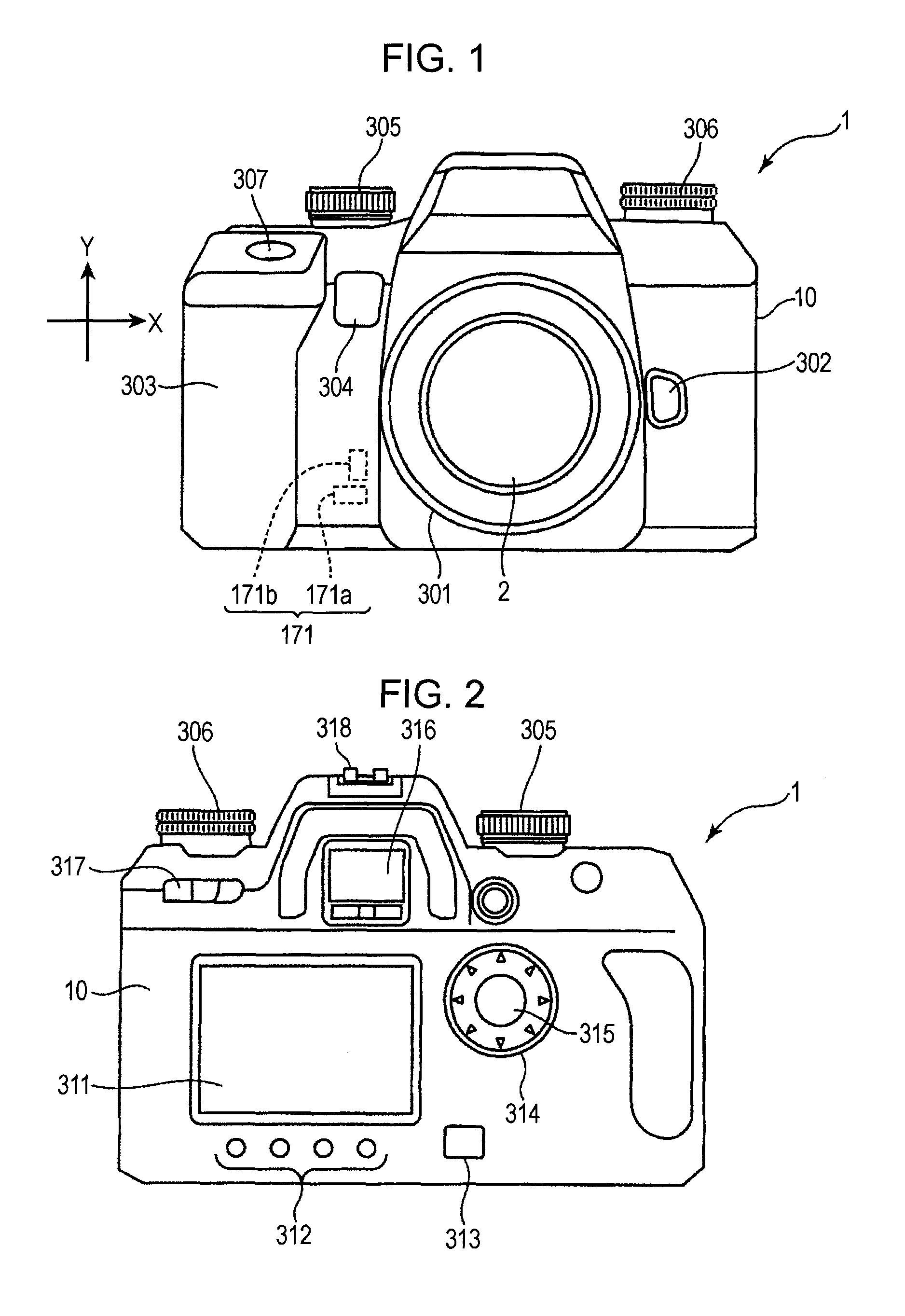
[0053]FIGS. 1 and 2 are views showing the exterior structure of a digital camera 1 (imaging apparatus) according to an embodiment of the present invention. FIG. 1 is a front exterior view of the digital camera 1, and FIG. 2 is a rear exterior view of the digital camera 1. As shown in FIG. 1, the digital camera 1 is a single-lens reflex type digital still camera including a camera body 10, and a taking lens 2 (interchangeable lens) detachably (interchangeably) mounted at substantially the center of the front surface of the camera body 10.

[0054]In FIG. 1, on the front surface side of the camera body 10, there are provided a mount section 301 which is located substantially at the center of the front surface and on which the taking lens 2 is mounted, a lens exchange button 302 arranged to the right of the mount section 301, a grip sectio...


PUM


Abstract

In an imaging apparatus with a shake correction function, the influence of front curtain shock is prevented from being exerted on a shake correction function section (shake correction drive). The imaging apparatus includes a shake detection sensor 171 that detects an amount of shake applied to a digital camera, a shake correction unit 200 that performs a shake correction drive of an imaging device 101 on the basis of a shake amount detection signal, a shutter unit 40 that is arranged immediately in front of the imaging device 101 and performs an optical-path opening operation and an optical-path blocking operation for opening and blocking an optical path of light guided to the imaging device 101, a timing control circuit 51 that supplies a predetermined reset signal to each pixel for each predetermined pixel line so as to start exposure on the imaging device 101, and a shutter control section 623 that controls exposure of the imaging device 101. At the time of shooting, the shutter control section 623 executes an electronic shutter control (electronic focal plane shutter) for starting exposure on the imaging device 101 by means of the reset signal supplied to each pixel from the timing control circuit 51.

Description

TECHNICAL FIELD[0001]The present invention relates to an imaging apparatus that incorporates a CMOS imaging device and performs shake correction by driving the imaging device, and more specifically to an imaging apparatus in which, depending on the situation, a front curtain can be effected by an electronic focal plane shutter and a rear curtain can be effected by a mechanical focal plane shutter.BACKGROUND ART[0002]As compared with an imaging device using a CCD (Charge Coupled Device), an imaging device using a CMOS (Complementary Metal Oxide Semiconductor) enables faster readout of pixel signals, less power consumption, and higher integration. Since such an imaging device can comply with requirements placed on an imaging apparatus in terms of size, performance, and the like, it has been attracting attention as an imaging device to be mounted on an imaging apparatus. Such a CMOS imaging device is also unique in enabling a so-called random scan whereby electric charge is read out by...

Claims


Application Information

Patent Timeline
Patent Type & Authority Patents(United States)
IPC IPC(8): H04N5/228H04N5/225
CPCG03B5/02H04N5/23248H04N5/2353H04N2101/00H04N23/68H04N23/73
Inventor MURASHIMA, NOBUHARUKIDO, TOSHIHITOTANAKA, YOSHIHARAUHONDA, TSUTOMU
Owner SONY CORP
Why Eureka
Try Eureka