Infrared remote-control signal transmitter
A signal transmitter, infrared remote control technology, applied in the field of infrared remote control, can solve the problems of being separated from the hardware platform, rarely seen in actual use, unable to achieve universal remote control, etc., to avoid trouble, wide application range, and simple operation.
- Summary
- Abstract
- Description
- Claims
- Application Information
AI Technical Summary
Problems solved by technology
Method used
Image
Examples
Embodiment 1
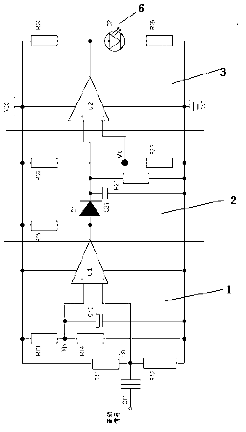
[0066] An infrared remote control signal transmitter, which includes the following parts:
[0067] Shell 4, input terminal 5, rectification circuit 1, integration circuit 2, square wave shaping transmitting circuit 3 and output terminal 6;
[0068] Wherein the input terminal 5 is an audio headphone plug;
[0069] There is a comparator U1 in the rectification circuit 1;
[0070] There is an integrating capacitor C21 in the integrating circuit 2;
[0071] There is a comparator U2 in the square wave shaping transmitting circuit 3;
[0072] The output terminal 6 is an infrared light emitting diode D2;
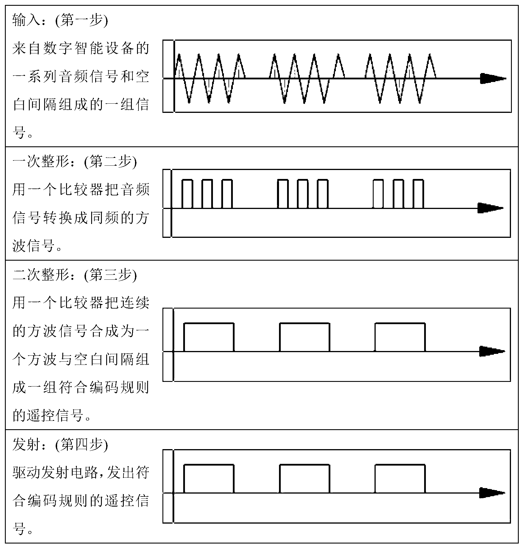
[0073] Its structure diagram and flow chart of audio signal processing are shown in figure 2 with image 3 ;
[0074] Specific as Figure 4 , Use 2 LM311 as the infrared remote control signal transmitter driven by the audio signal of 2 comparators U1 and U2. You can take R13=R14, which is on the order of thousands of ohms; take R12 to be 5% to 50% larger than R11, which is o...
Embodiment 2
[0076] An infrared remote control signal transmitter, which includes the following parts:
[0077] Shell 4, input terminal 5, rectification circuit 1, integration circuit 2, square wave shaping transmitting circuit 3 and output terminal 6;
[0078] Wherein the input terminal 5 is an audio headphone plug;
[0079] The rectification circuit 1 is a full bridge rectification circuit composed of 4 diodes (D11, D12, D13, D14);
[0080] There is an integrating capacitor C1 in the integrating circuit 2;
[0081] There is a comparator U3 in the square wave shaping transmitting circuit 3;
[0082] The output terminal 6 is an infrared light emitting diode D2;
[0083] Its structure diagram and flow chart of audio signal processing are shown in Figure 5 with Image 6 ;
[0084] Specific as Figure 7 , An infrared remote control signal generator driven by an audio signal using a LM393 as a comparator. The rectification circuit 1 is a full-bridge rectification circuit composed of 4...
Embodiment 3
[0086] Figure 8 It is a touch screen interface of a mobile phone remote control program designed for a certain city's IPTV. With these buttons, you can control the IPTV set-top box, choose to watch all the TV programs broadcast by IPTV and watch all the programs stored in IPTV on demand, which meets all our daily requirements for watching IPTV. Figure 9 Is the block diagram of the mobile phone remote control program. In the initialization stage, while drawing the touch screen interface, the program should increase the output volume of the mobile phone to around 2 / 3 of the maximum output volume, and then send out a continuous audio signal of several hundred milliseconds to pre-set the infrared remote control signal transmitter. thermal and capacitive charging. After a button on the touch screen is pressed, it is necessary to check and adjust the output volume of the mobile phone to around 2 / 3 of the maximum output volume, and then play the intermittent audio signal accordin...
PUM
 Abstract
Description
Claims
Application Information
 - R&D
- Intellectual Property
- Life Sciences
- Materials
- Tech Scout
- Unparalleled Data Quality
- Higher Quality Content
- 60% Fewer Hallucinations
Browse by: Latest US Patents, China's latest patents, Technical Efficacy Thesaurus, Application Domain, Technology Topic, Popular Technical Reports.
© 2025 PatSnap. All rights reserved.Legal|Privacy policy|Modern Slavery Act Transparency Statement|Sitemap|About US| Contact US: help@patsnap.com


