Integrated coherent-light-communication electro-optical modulator structure

An electro-optical modulator and coherent optical communication technology, which is applied in instruments, optics, nonlinear optics, etc., can solve the problems of low optical bandwidth, high stability, and low power consumption, and achieve high optical bandwidth, high stability, and power consumption. The effect of low consumption

Active Publication Date: 2013-05-08
宏芯科技(泉州)有限公司
View PDF5 Cites 11 Cited by
  • Summary
  • Abstract
  • Description
  • Claims
  • Application Information

AI Technical Summary

Benefits of technology

This patented innovation allows an optoeletronic module (EOM) used in coherence optics communications to have both light split function and 90° phase shifting capabilities. It achieves these benefits by having very wide optically active regions at different angles around its surface or inside which are designed specifically for specific types of signals called polarization modes. These modules also include certain features like amplification stages and signal processing circuits, making them ideal for use in long distance transmission systems where there may be changes over time caused by temperature fluctuations. Overall, they offer technical advantages such as compactness, reduced energy usage, lower costs, higher reliability, ease of integration into electronic devices, etc., leading to improved performance and functionality within various applications involving telecommunicational equipment.

Problems solved by technology

Technologies aim towards improving integration between electronic componentry and optically active media within optoeletronics modules called CMOS Intermediate Passage Components (CIC), resulting in improved performance capabilities over existing technologies. One approach involves embedding these components into hybrid fiber coaxial cable(HFC)-based photonic crystal fibre (PCF) converger module designs without compromising electromagnetic conversion properties. Another option includes incorporate integrated circuits onto chip packages instead of separate parts, but there may also exist methods involving modifying the physical dimensions of the passives themselves during manufacture.

Method used


Image

  • Integrated coherent-light-communication electro-optical modulator structure
  • Integrated coherent-light-communication electro-optical modulator structure
  • Integrated coherent-light-communication electro-optical modulator structure

Examples


Embodiment Construction

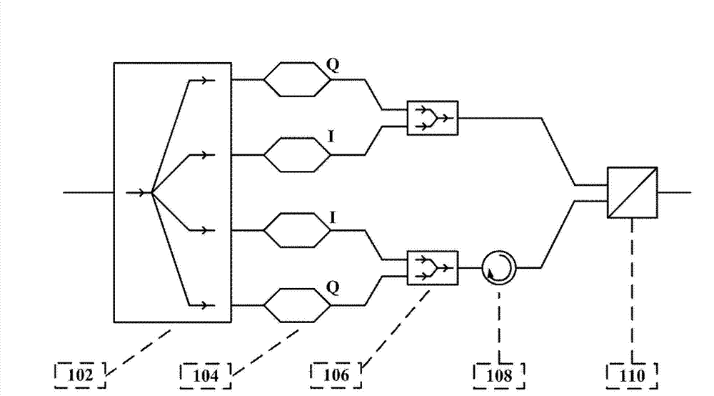
[0023] see figure 1 As shown, the present invention provides an integrated electro-optical modulator structure for coherent optical communication, including:

[0024] An optical beam splitter 102, which has an input end, a multimode waveguide region and four output ends, the light intensity of the output light fields of the four output ends is equal, and the phases of the two output light fields on the outside are the same as those of the two in the center. The phases of the two output light fields differ by 90 degrees, and the optical beam splitter 102 is realized by a 1×4 multimode interference coupler. The multimode interference coupler is made of materials with a refractive index difference greater than 30%. The material of the multi-mode interference coupler is silicon and silicon dioxide, which facilitates the preparation of devices by using the mature complementary metal oxide semiconductor (CMOS, Complementary Metal Oxide Semiconductor) technology in the microelectron...


PUM


Abstract

Disclosed is an integrated coherent-light-communication electro-optical modulator structure which comprises a light beam splitter, four electro-optical modulators, two light beam combiners, a polarization rotator and a polarization beam combiner. The light beam splitter is provided with an input port, a multimode waveguide region and four output ports, wherein light intensities of light fields output by the four output ports are equal, and difference of two outside phases outputting light fields and two middle phases outputting light fields is 90 degrees; input ports of the four electro-optical modulators are connected with four output ports of the light beam splitter; each light beam combiner is provided with two input ports, a multimode waveguide region and an output port, wherein the input port of each light beam combiner is connected with output ports of two electro-optical modulators on one side of the four electro-optical modulators; the input port of the polarization rotator is connected with the output ports of the light beam combiners; and one input port of the polarization beam combiner is connected with the output port of one polarization rotator, and the other input port of the polarization is connected with the other output port of the two light beam combiners.

Description


Claims


Application Information

Patent Timeline
Owner 宏芯科技(泉州)有限公司
Why Eureka
Try Eureka