Distributed 3D multi-channel rendering method, system and platform

A rendering system and multi-channel technology, applied in the field of distributed multi-machine parallel computing, can solve problems such as expensive, unable to render pictures, change customers, etc., to achieve the effect of improving resource utilization, increasing display frame rate, and high scalability

Active Publication Date: 2016-03-30
GUANGDONG VTRON TECH CO LTD
View PDF0 Cites 0 Cited by
  • Summary
  • Abstract
  • Description
  • Claims
  • Application Information

AI Technical Summary

Problems solved by technology

[0005] (1) The hardware configuration of the rendering node machine is generally required to be the same, and the rendering output resolution is also required to be the same. Otherwise, when roaming the scene, a low-end hardware configuration will inevitably reduce the display frame of the entire cluster system when encountering a complex scene. Rate;
[0006] (2) Each rendering node can only render a fixed segmented content of the entire scene wall. For example, if the entire scene wall is rendered by two nodes, rendering node 1 can only render the content of the left side of the scene wall. Rendering node 2 can only render the content on the right side of the screen, that is to say, rendering node 1 cannot render the content on the right side of the screen during rendering
At present, the existing distributed 3D rendering solution is to use high-end display cards to replace the original low-end display cards. In this way, due to the high cost of high-end display cards, the cost of viewing 3D applications on the customer's splicing wall is increased.
On the other hand, in practice, it is necessary to change the original configuration of the customer, and it will cause waste to the original computer system configuration, which is not conducive to the promotion of 3D visualization applications among customers

Method used


Image

  • Distributed 3D multi-channel rendering method, system and platform
  • Distributed 3D multi-channel rendering method, system and platform
  • Distributed 3D multi-channel rendering method, system and platform

Examples


Embodiment Construction

[0034] The present invention will be further described in detail below in conjunction with the embodiments and drawings, but the implementation of the present invention is not limited thereto.

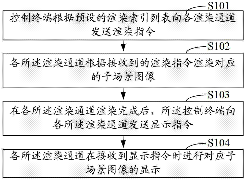
[0035] see figure 2 As shown, it is a schematic flowchart of an embodiment of the distributed 3D multi-channel rendering method of the present invention. Such as figure 2 As shown, the distributed 3D multi-channel rendering method in this embodiment includes the following steps:

[0036] Step S101: The control terminal sends rendering instructions to each rendering channel according to the preset rendering index list, and enters step S102, wherein the rendering index list covers the sub-scene images that need to be rendered by each rendering channel corresponding to the overall scene image of each frame, etc. Content, before rendering, the rendering index list can be configured according to the rendering capabilities of each rendering channel and the overall scene image of each fra...


PUM


Abstract

The present invention provides a distributed 3D multi-channel rendering method, system and platform. The method includes the steps of: the control terminal sends a rendering instruction to each rendering channel according to a preset rendering index list; Render the corresponding sub-scene image; after the rendering of each rendering channel is completed, the control terminal sends a display instruction to each of the rendering channels; each of the rendering channels displays the corresponding sub-scene image when receiving the display instruction. The present invention can improve the resource utilization rate of the rendering channel, can effectively improve the display frame rate of the three-dimensional visualization application of the mosaic wall, better embodies the characteristics of computer parallel collaborative work, and can be quickly integrated with the existing mosaic wall system, and has high scalability. It is convenient to promote the 3D visualization application of video wall.

Description

technical field [0001] The invention relates to the field of distributed multi-computer parallel computing, in particular to a distributed 3D multi-channel rendering method, system and platform. Background technique [0002] 3D rendering is to complete the image conversion process from the three-dimensional scene data generated in the computer to the two-dimensional display plane, and the most widely used in practice is the 3DGIS rendering system. The 3DGIS system is the organic combination of three-dimensional visual rendering and geographic information system. . 3D visualization technology has been widely used in military, aviation, aerospace, medicine, geological exploration, cultural entertainment and artistic modeling. [0003] figure 1 It is an existing 3D multi-channel rendering method based on a distributed computer architecture. The distributed multi-channel stores 3D data on different computer nodes to achieve parallel rendering processing. The entire cluster is ...

Claims


Application Information

Patent Timeline
Patent Type & Authority Patents(China)
IPC IPC(8): G06T15/00G09G5/14
Inventor 肖平
Owner GUANGDONG VTRON TECH CO LTD
Why Eureka
Try Eureka