
Sound cavity, sound cavity system and mobile terminal

A sound cavity and sound hole technology, applied in the field of mobile terminals, can solve the problems of affecting the sound quality of mobile phones, the low-frequency playback effect of the mobile phone sound cavity, and the sharp sound of mobile phone playback, so as to improve the playback effect of medium and low frequencies and improve the sound quality. Effect

Inactive Publication Date: 2013-05-22
ZTE CORP
View PDF5 Cites 3 Cited by
  • Summary
  • Abstract
  • Description
  • Claims
  • Application Information

AI Technical Summary

Problems solved by technology

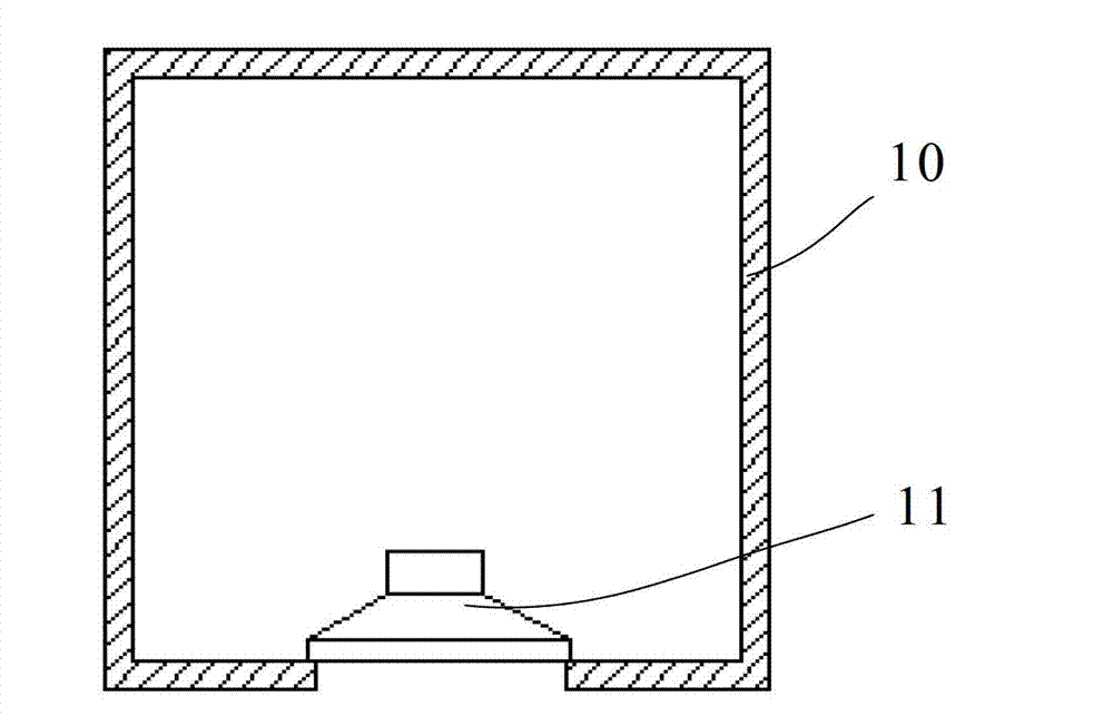
[0003] like figure 1 As shown, the airtight sound cavity includes: a housing 10 with a speaker sound outlet and a speaker 11 installed at the position of the speaker sound outlet of the housing 10; The sound wave is isolated to eliminate the acoustic short-circuit interference; however, the sound cavity of this structure is limited by the physical size of the unit and the corresponding acoustic indicators, and cannot obtain a better mid-low frequency playback effect, resulting in sharp sound and poor sound quality when playing on mobile phones
Especially under the development trend of ultra-thin mobile phone structure, the volume size of the sound cavity of the mobile phone is also reduced. For the same speaker unit, as the volume of the closed sound cavity of the mobile phone is reduced, the mid-low frequency playback effect of the sound cavity of the mobile phone is also reduced. Then it gets worse, which affects the sound quality of the phone

Method used


Image

  • Sound cavity, sound cavity system and mobile terminal
  • Sound cavity, sound cavity system and mobile terminal
  • Sound cavity, sound cavity system and mobile terminal

Examples


Embodiment Construction

[0024] With the development of miniaturization and ultra-thin structure of mobile terminals, the volume of sound chambers applied to mobile terminals is also reduced. For the same speaker unit, with the reduction of the volume of airtight sound chambers of mobile phones, the volume of sound chambers of mobile terminals is reduced. The playback effect of the middle and low frequencies becomes worse accordingly, thereby affecting the sound quality of the mobile terminal.

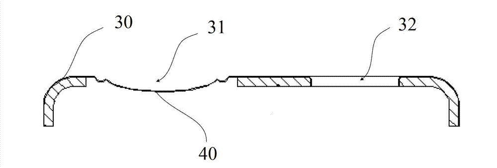
[0025] In view of this, the present invention provides an improved technical solution, adding a passive radiator on the airtight sound cavity system of the loudspeaker, and using the passive radiator diaphragm as the passive radiation sound source of the sound cavity to replace the passive radiation Because the passive radiator diaphragm does not occupy the internal space of the sound cavity, the internal space of the sound cavity can be utilized to the maximum extent, and the low-frequency playback range of th...


PUM


Abstract

The invention relates to the technical field of mobile terminals, in particular to a sound cavity, a sound cavity system and a mobile terminal. The sound cavity, the sound cavity system and the mobile terminal are used for improving playing effects of a low and medium frequency in the airtight sound cavity and improving tone quality of the mobile terminal. The sound cavity comprises a shell body and a passive radiator vibrating diaphragm, wherein the shell body is provided with a loudspeaker sound-out hole and a passive radiator open hole and the passive radiator vibrating diaphragm is used for covering the passive radiator open hole. Curved loops are arranged around the passive radiator vibrating diaphragm. The passive radiator vibrating diaphragm is used as a passive radiating sound source of the sound cavity. Because inner space of the sound cavity is not occupied by the passive radiator vibrating diaphragm, the inner space of the sound cavity can be utilized in maximum limit. Therefore, the playing effects of the low and medium frequency of the sound cavity can be improved and the tone quality of the mobile terminal can be improved. The invention further discloses a sound cavity system at the same time. The sound cavity system is provided with the sound cavity which has above characteristics. The invention further discloses a mobile terminal, and the mobile terminal is provided with the sound cavity system which has above characteristics.

Description

technical field [0001] The invention relates to the technical field of mobile terminals, in particular to a sound cavity, a sound cavity system and a mobile terminal. Background technique [0002] With the wide application of mobile phones, higher requirements are put forward for the sound quality of mobile phones; one of the important factors affecting the sound quality of mobile phones is the structure of the sound cavity of mobile phones. In order to obtain better low-frequency effects and greater loudness, most of the sound Airtight cavity structure. [0003] Such as figure 1 As shown, the airtight sound cavity includes: a housing 10 with a speaker sound outlet and a speaker 11 installed at the position of the speaker sound outlet of the housing 10; The sound wave is isolated to eliminate the acoustic short-circuit interference; however, the sound cavity of this structure is limited by the physical size of the unit and the corresponding acoustic indicators, and cannot ...

Claims


Application Information

Patent Timeline
Patent Type & Authority Applications(China)
IPC IPC(8): H04R1/20H04R7/02H04M1/62
Inventor 冯健宏
Owner ZTE CORP
Learn More