Ultra-thin loudspeaker box for flat-panel televisions
A flat-panel TV, ultra-thin technology, applied in the direction of frequency/direction characteristic devices, etc., can solve the problems of limited amplitude of the sound cone, difficulty in improving low-frequency performance, poor applicability, etc., to achieve improved low-frequency effects, excellent low-frequency effects, and good applicability Effect
- Summary
- Abstract
- Description
- Claims
- Application Information
AI Technical Summary
Problems solved by technology
Method used
Image
Examples
Embodiment 1
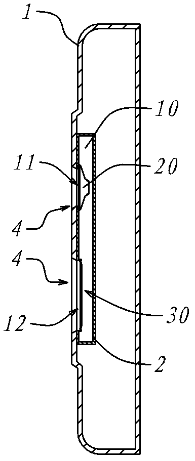
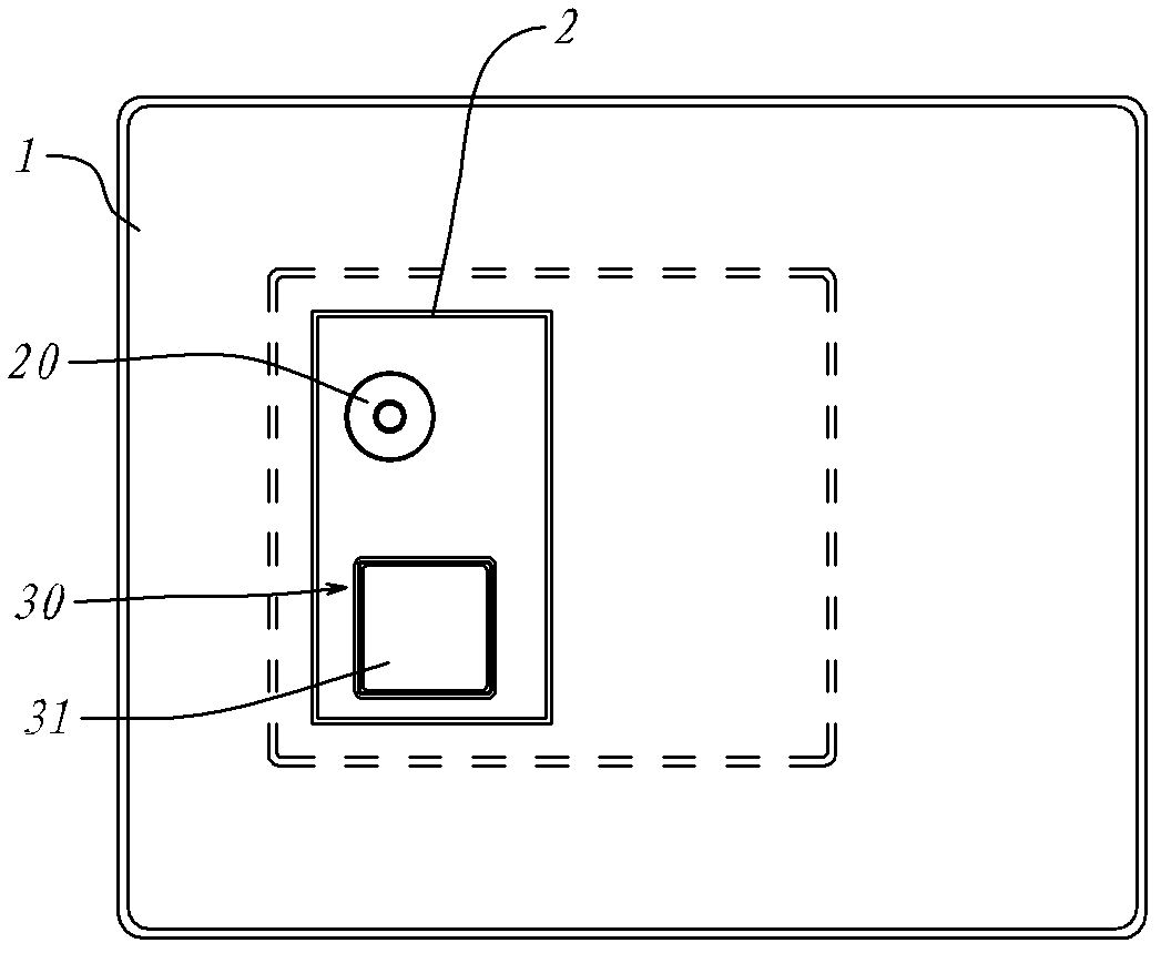
[0038] figure 1 It is a schematic cross-sectional view of Embodiment 1 of the present invention applied in the back shell of a flat-panel TV; figure 2 yes figure 1 The schematic diagram of the front view of the embodiment; image 3 yes figure 1 Embodiment enlarged sectional schematic diagram; In conjunction with these three figures, illustrate:
[0039] The back shell 1 is the back cover of a large-screen flat-panel TV, and the sound box body 2 is fixed on the inner wall of the back shell 1 . Inside the speaker body 2 is a resonant cavity 10 , which is a flat box whose thickness is smaller than its length and width, so its thickness direction can be properly placed in the thickness of the rear shell 1 . There is a sound cone hole 11 and a diaphragm hole 12 on the inner wall of the resonance cavity 10, the sound cone hole 11 cooperates with a loudspeaker unit 20 located in the rear loading mode inside the resonance cavity 10; the diaphragm hole 12 has a built-in passive ra...
Embodiment 2
[0042] Figure 4 It is a schematic cross-sectional view of the second embodiment of the present invention; compared with the first embodiment, the effective cone diameter of the speaker unit 20 of this embodiment is greater than the maximum thickness of the resonant cavity 10, so that the speaker unit has a larger load. At the same time, the resonant cavity 10 is no longer an independent space in the speaker body, but is formed together with the rear shell 1 through a sound box cover 3, so that the sound cone hole 11 and the diaphragm hole 12 are directly connected to the sound hole 4 on the rear shell 1. Multiplexing is realized, so that compared with Embodiment 1, the speaker unit 20 and the passive radiation unit 30 are closer to the back outer wall of the rear shell 1, a larger amplitude space of the speaker and diaphragm can be obtained, and a better low-frequency effect can be obtained. In appearance, the passive diaphragm 31 on the passive radiation unit 30 directly bec...
Embodiment 3
[0044] Such as Figure 5 , a schematic cross-sectional view of the third embodiment of the present invention; and Figure 4 Compared with the second embodiment shown, the diaphragm hole 12 of the passive radiation unit 30 is also placed directly on the back shell 1, and the resonant cavity 10 is also jointly formed by the sound box cover 3 and the back shell 1. The difference is that, The cone hole 11 is placed on the resonance cavity opposite to the cone hole 12, and the speaker unit 20 is loaded on the cone hole 11 in a front-loading manner, and its body is located outside the resonance cavity. This is a special occasion, where the entire resonant cavity is limited and cannot accommodate the thickness of the speaker unit 20, the volume of the speaker unit 20 can be avoided according to the rear of the sound box cover 3 and the positions of other devices inside the device.
PUM
 Abstract
Description
Claims
Application Information
 - R&D
- Intellectual Property
- Life Sciences
- Materials
- Tech Scout
- Unparalleled Data Quality
- Higher Quality Content
- 60% Fewer Hallucinations
Browse by: Latest US Patents, China's latest patents, Technical Efficacy Thesaurus, Application Domain, Technology Topic, Popular Technical Reports.
© 2025 PatSnap. All rights reserved.Legal|Privacy policy|Modern Slavery Act Transparency Statement|Sitemap|About US| Contact US: help@patsnap.com


