Twist drill with helical cutting flank

A flank and helical technology, applied in the field of twist drills, can solve problems such as stress concentration, failure to achieve smooth transition, and affect the use effect, so as to avoid stress concentration

CN103128346BActive Publication Date: 2015-11-25大连远东工具有限公司
8 Cites 0 Cited by

Patent Information

Authority / Receiving Office
CN · China
Patent Type
Patents(China)
Current Assignee / Owner
Publication Date
2015-11-25

Smart Images

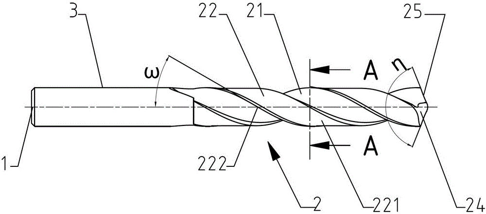
  • Figure 1
    Figure 1
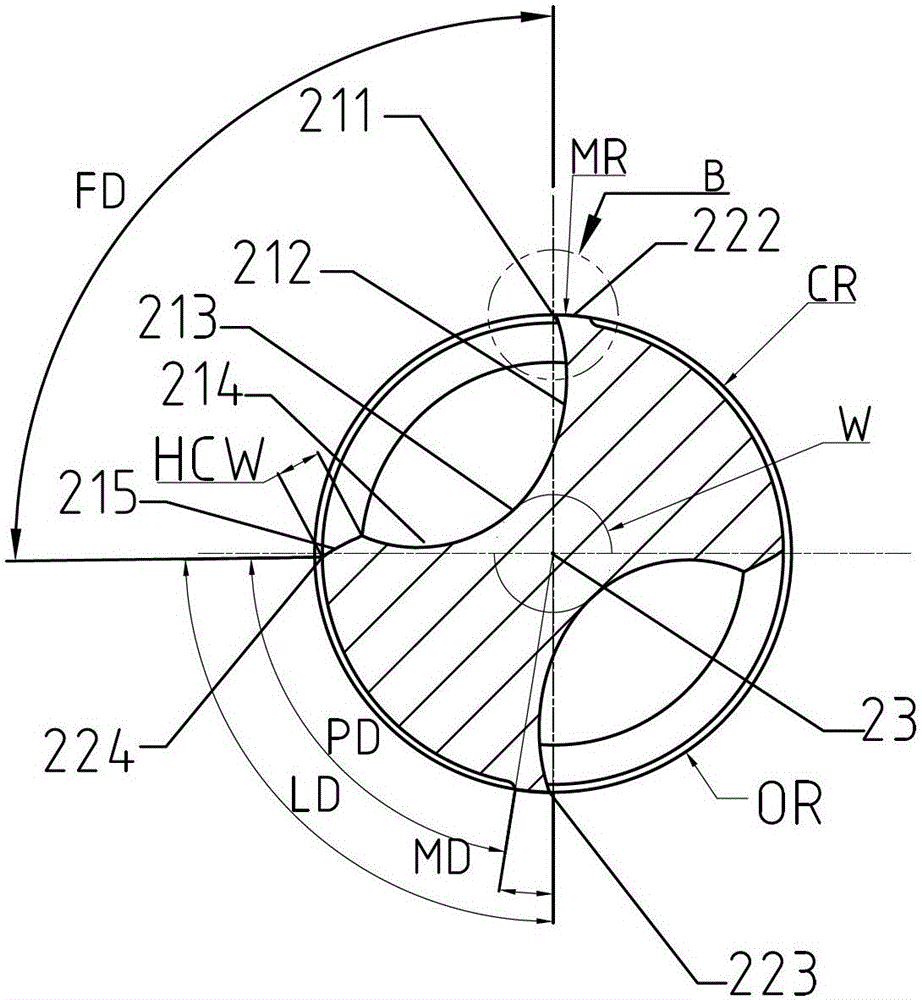
  • Figure 2
    Figure 2
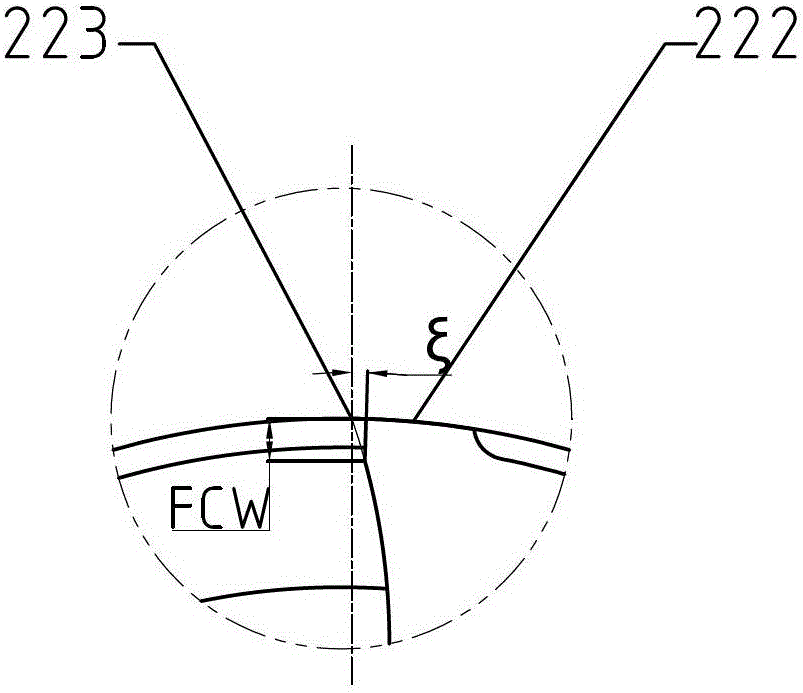
  • Figure 3
    Figure 3
Patent Text Reader

Abstract

The invention discloses a twist drill with a spiral cutting back tool. The twist drill with the spiral cutting back tool comprises a cutting portion which rotates around an axis and a handle portion which matches with a jacket. Two grooves which extend from the front end of the cutting portion to the handle portion in a spiral mode and are sued for discharging cutting chips are formed in the cutting portion. The cutting portion is further provided with blade backs which are respectively connected with the periphery of the two grooves. The twist drill with the spiral cutting back tool is characterized in that the grooves form two spiral cutting back tool faces at the front end of the cutting portion, the two cutting back tool faces are intersected in a drill core position to form an S-shaped drill core cutting blade and two main cutting blades, the main cutting blade is connected with the S-shaped drill core cutting blade through a cutting blade connection portion in a smooth mode, each cutting back tool face begins from the main cutting blade and is formed by smoothly connecting a main back blade face, a transition face and a the cutting back tool face stop face. According to the twist drill with the spiral cutting back tool, the spiral cutting back tool faces are intersected to form the S-shaped drill core cutting blade which is connected with the main cutting blade in a smooth mode, stress concentration is greatly reduced, drilling load and centring capacity are further improved, and the twist drill with the spiral cutting back tool is easy to be widely popularized.
Need to check novelty before this filing date? Find Prior Art

Description

technical field

[0001] The invention relates to a drill bit, in particular to a twist drill with a helical cutting flank. Background technique

[0002] The helical flank drill bit is a new type of drill bit compared with the flat flank, conical flank, cylindrical flank and other drill bits. Due to the cutting process of shear slippage, the axial penetration force is small during cutting; due to the limitation of the structure, the chisel edge of the drill bit such as planar, conical, and cylindrical drills is actually subjected to extrusion grinding, so the chisel edge It is easy to wear, and has a large axial penetration force during cutting; in addition, it also greatly enhances the centering ability of the drill bit.

[0003] However, due to the limitation of the technical level of the early helical flank drill bit, the excessively large relief angle at the junction of the chisel edge and the main cutting edge often caused edge chipping and weakened the strength of the d...

Examples

Embodiment Construction

[0040] Such as figure 1 As shown, a twist drill with a helical cutting flank includes a cutting part 2 that rotates around the axis 1 and a shank 3 that matches the jacket. The cutting part 2 is provided with two The front end of the cutting part 2 spirally extends toward the shank part 3 to discharge the groove 21 for cutting chips. The cutting part 2 is also provided with a blade back 22 respectively connecting the outer peripheral edges of the two grooves 21. The groove 21 is a groove extending along the axis 1 with a helix angle of ω and a radial section corresponding to an arc length of FD (such as figure 2 shown), including the groove front end connection part 211, the groove front end 212, the groove bottom 213, the groove end 214 and the groove end connection part 215, the groove front end 212, the groove bottom 213 and the The groove end 214 is on the same smooth curve, wherein, ω=0°~60°; the blade back 22 includes a clearing area 221, a margin 222, a peripheral cu...