Motor vehicle flashing signal light and method for operating flashing signal light

A technology for signal lights and motor vehicles, applied in optical signals, signal devices, vehicle parts, etc., can solve problems such as flashing signal lights, and achieve the effect of improving the degree of conspicuousness and reducing the attention time.

Inactive Publication Date: 2013-06-05
AUDI AG
View PDF8 Cites 9 Cited by
  • Summary
  • Abstract
  • Description
  • Claims
  • Application Information

AI Technical Summary

Problems solved by technology

But it is technically impossible to make all the flashing lights flash at exactly the same moment

Method used


Image

  • Motor vehicle flashing signal light and method for operating flashing signal light
  • Motor vehicle flashing signal light and method for operating flashing signal light
  • Motor vehicle flashing signal light and method for operating flashing signal light

Examples


Embodiment Construction

[0026] These examples are preferred implementation forms of the invention.

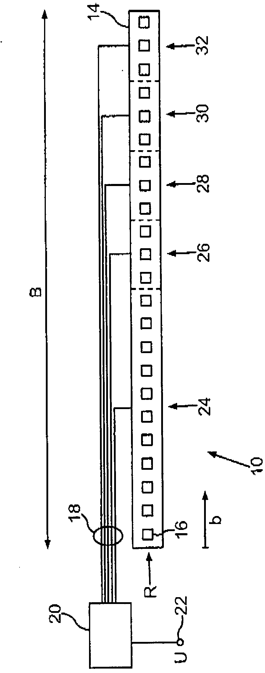
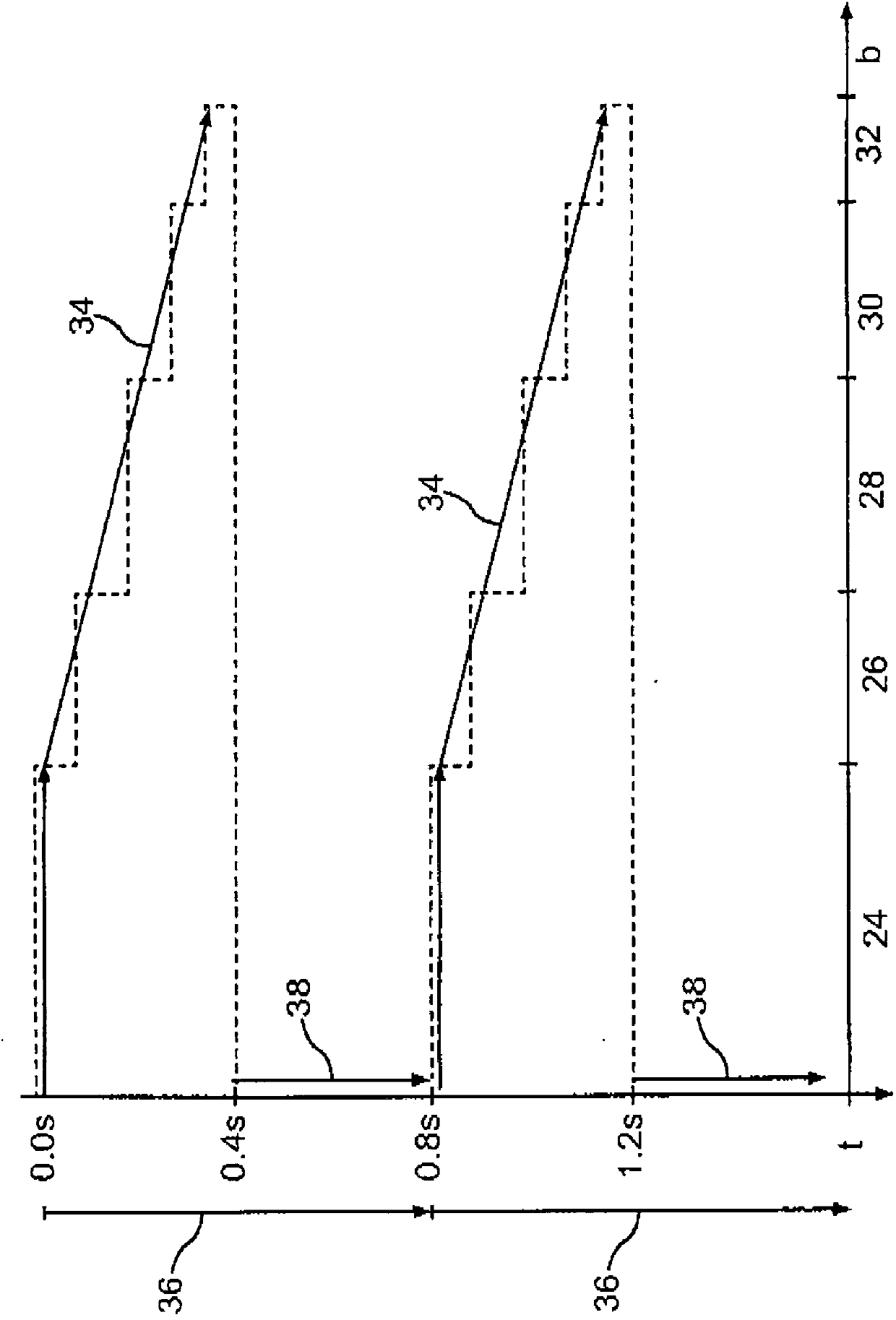
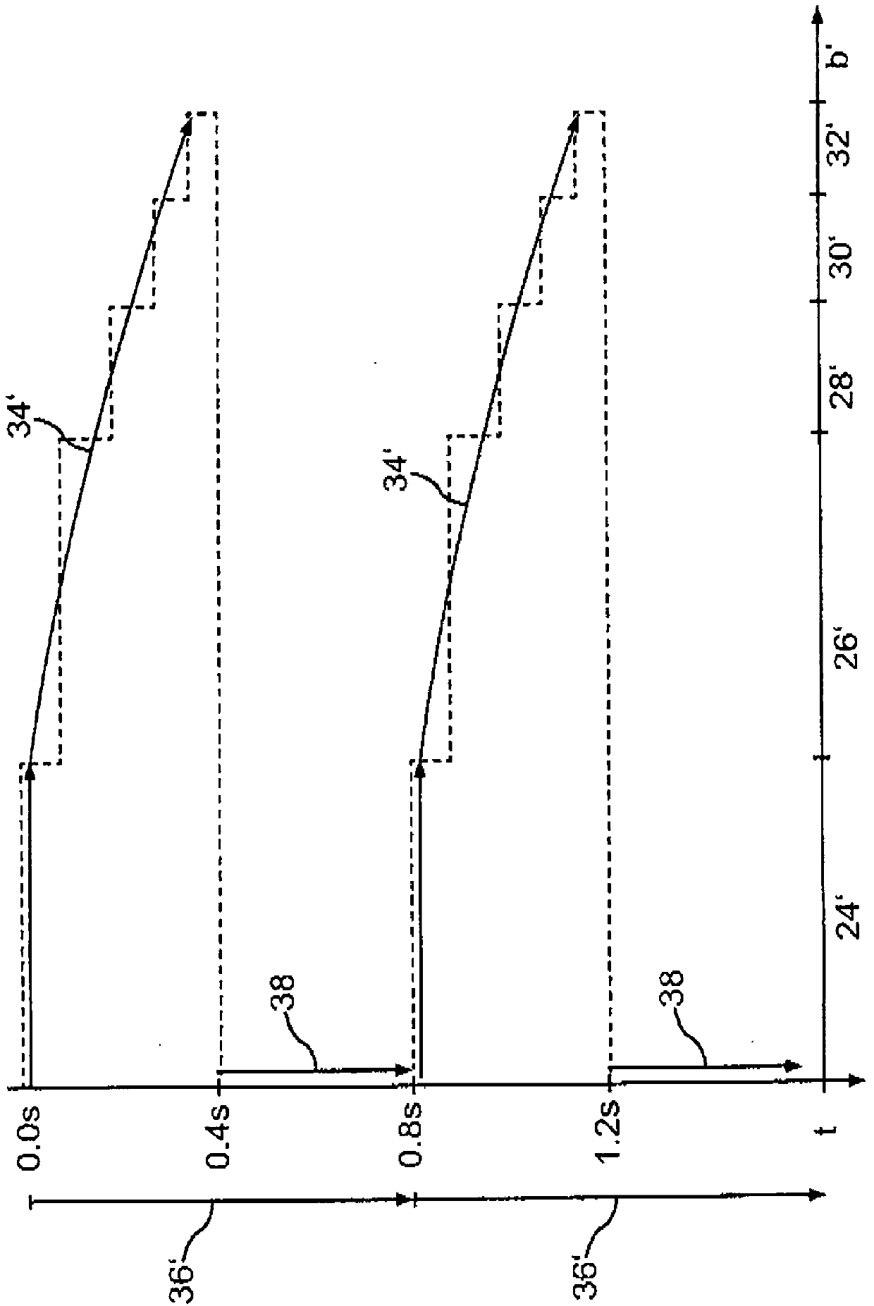
[0027] exist figure 1 Shown in is the interior of the blinker 10 . The blinker 10 is built into a rear light of a passenger car. A printed circuit board 14 (Printed Circuit Board—PCB) is located in the blinker 10 , on which a total of twenty-three light-emitting diodes 16 are soldered. For clarity, figure 1 Only one of the light-emitting diodes 16 in has a reference numeral. Here, the light emitting diodes 16 are arranged in a straight line on the printed circuit board 14 . The circuit board 14 is located behind the orange transparent glass in the blinker. The light of the light-emitting diodes 16 therefore appears orange to the observer from the outside. Instead of a single printed circuit board 14 , it is also possible to distribute the light-emitting diodes over several printed circuit boards.

[0028] The printed circuit board 14 is connected to the control unit 20 via a plurality of wires ...


PUM


Abstract

The invention relates to a motor vehicle flashing signal light which can highlight a driving direction to be indicated through changing light effects. But not all countries allow indicating a change of the driving direction by means of changing light. The invention aims to improve indication of the change of the driving direction for a motor vehicle. For this purpose, according to the invention, an LED flashing signal light (10) is operated through the following method: in a flashing cycle, starting from a switched-off state of all LED groups (24-32) of the flashing signal light, a primary group (24) is switched on at first, and subsequently the other LED groups (26-32) are successively switched on until all the LED groups (24-32) are switched on. The LED groups (24-32) are maintained in a switched-on state for a predetermined time period and are finally switched off. The time period from activation of the primary group (24) until reaching the active state of all LED groups (24-32) lies in the range of 100 milliseconds to 200 milliseconds.

Description

technical field [0001] The invention relates to a motor vehicle blinker with a plurality of light emitting diodes (LED-Light emitting diodes) arranged in a row. The invention also relates to a method for operating a blinker, in which a plurality of LED groups each comprising at least one light-emitting diode are arranged in a row. Background technique [0002] Strobe lights of this type are known, for example, from DE 101 30 259 A1 and US 2009 / 0051523 A1. [0003] Strobe lights, or simply flashers / turn signals, are used in motor vehicles as direction indicators. The blinkers are alternately switched on and off within a flash cycle, that is, each flash cycle consists of an active period (during which the blinker lights up) and an inactive period (during which the blinker remains dark) . Here, the flash frequency is between 1 Hz and 2 Hz. For flashing lights to be permitted in road traffic, certain legal framework conditions must be fulfilled here. It must therefore be vi...

Claims


Application Information

Patent Timeline
Patent Type & Authority Applications(China)
IPC IPC(8): B60Q1/38
CPCB60Q1/38B60Q1/34B60Q2900/40B60Q1/381
Inventor M·斯塔德勒T·施沃兹R·兰德勒B·胡梅尔
Owner AUDI AG
Why Eureka
Try Eureka