
Measuring method of banding clearance of movable vane of rotor of steam turbine and clamping device

A technology of steam turbine rotor and shroud gap, applied in mechanical gap measurement and other directions, can solve the problem of difficult shroud gap measurement, achieve the effect of convenient and effective measurement, and ensure repeatability and accuracy

Active Publication Date: 2013-06-12
SHANGHAI ELECTRIC POWER GENERATION EQUIPMENT CO LTD
View PDF4 Cites 2 Cited by
  • Summary
  • Abstract
  • Description
  • Claims
  • Application Information

AI Technical Summary

Problems solved by technology

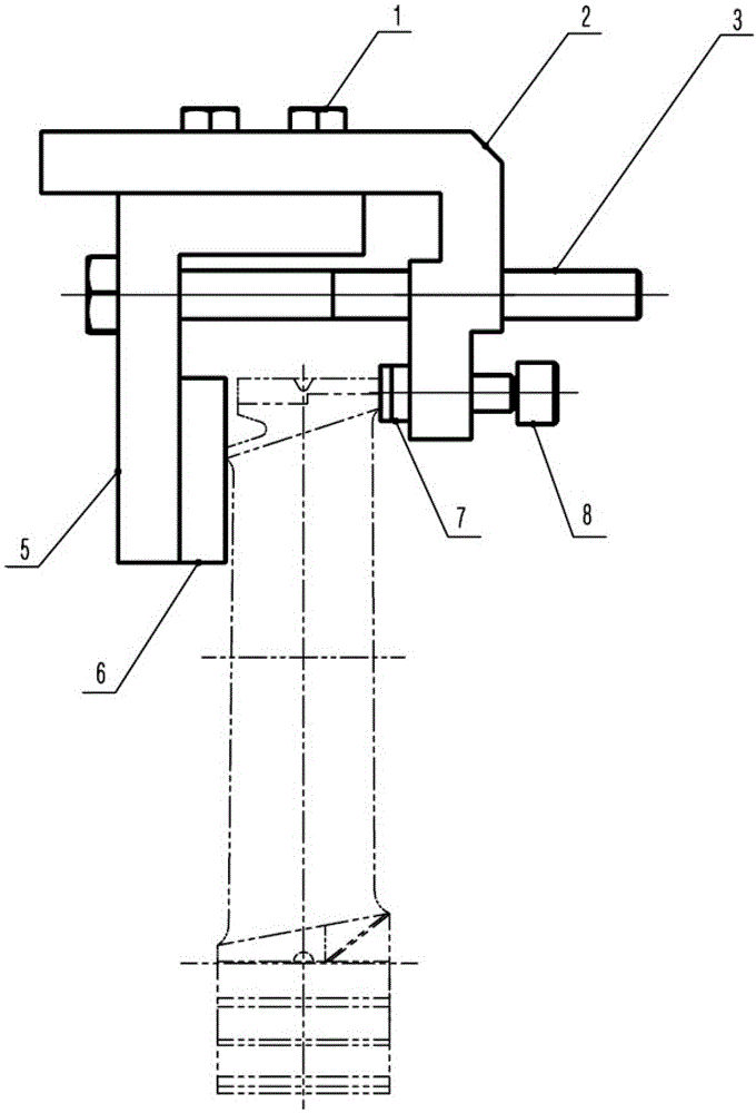
[0004] In view of the above-mentioned shortcomings of the prior art, the object of the present invention is to provide a method and clamping device for measuring the shroud clearance of the moving blade of the steam turbine rotor, which is used to solve the problem of difficult measurement of the shroud clearance after the assembly of the steam turbine in the prior art

Method used


Image

  • Measuring method of banding clearance of movable vane of rotor of steam turbine and clamping device
  • Measuring method of banding clearance of movable vane of rotor of steam turbine and clamping device

Examples


Embodiment Construction

[0028] The implementation of the present invention will be illustrated by specific specific examples below, and those skilled in the art can easily understand other advantages and effects of the present invention from the contents disclosed in this specification.

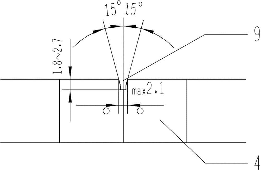
[0029] see Figure 1 to Figure 2 . It should be noted that the structures, proportions, sizes, etc. shown in the drawings attached to this specification are only used to match the content disclosed in the specification, for those who are familiar with this technology to understand and read, and are not used to limit the implementation of the present invention. Limiting conditions, so there is no technical substantive meaning, any modification of structure, change of proportional relationship or adjustment of size, without affecting the effect and purpose of the present invention, should still fall within the scope of the present invention. The disclosed technical content must be within the scope covered. At the sa...


PUM

PropertyMeasurementUnit
Depthaaaaaaaaaa
Opening angleaaaaaaaaaa
Widthaaaaaaaaaa

Abstract

The invention provides a measuring method of a banding clearance of a movable vane of a rotor of a steam turbine and a clamping device. The clamping device comprises a first clamping arm and a second clamping arm, which are connected, wherein an adjusting bolt used for adjusting a distance between the first clamping arm and the second clamping arm penetrates through the first clamping arm and the second clamping arm, a thimble is arranged on one side of the first clamping arm, which faces the second clamping arm, and a top plate is arranged on one side of the second clamping arm, which faces the first clamping arm. The measuring method, provided by the invention, is convenient and effective, a clearance is formed at a set torsion value by a shroud ring and is measured, so that tightness of the shroud ring is measured; furthermore, manual location and clamping can be replaced by the clamping device provided by the invention, and the torsion value is ensured to be known and fixed, so that a certain clearance is generated at the set torsion by the shroud ring, and measuring repeatability and measuring accuracy can be ensured.

Description

technical field [0001] The invention relates to a method for measuring the shroud gap of the moving blade of a steam turbine rotor, in particular to a measuring method and a clamping device for the shroud gap of the moving blade of the steam turbine rotor. Background technique [0002] The steam turbine shroud is installed on the top of the blade, and some blades have their own shroud. Since the collision damping between the shrouds and the overall design of the blade should be considered, the damping can provide the overall rigidity of the blade, so the tightness of the shrouds plays a key role in the safe operation of the blade. The shroud with steam seal can form a closed channel with the blade to reduce the leakage loss of the blade top. During the operation and use of the steam turbine, the steam turbine blade shroud gap monitor is generally used for real-time monitoring. The monitor includes a lot of multiple measurements of the gap between the fixed parts of the stea...

Claims


Application Information

Patent Timeline
IPC IPC(8): G01B5/14
Inventor 胡宇光顾剑勇李静
Owner SHANGHAI ELECTRIC POWER GENERATION EQUIPMENT CO LTD
Learn More