Driving device

A technology of driving device and moving parts, applied in focusing device, electromechanical device, installation, etc., can solve problems such as material selection limitation of contact rod, and achieve the effect of avoiding alignment problem, small height and simplifying assembly process

Inactive Publication Date: 2013-06-26
HONG FU JIN PRECISION IND (SHENZHEN) CO LTD +1
View PDF5 Cites 4 Cited by
  • Summary
  • Abstract
  • Description
  • Claims
  • Application Information

AI Technical Summary

Problems solved by technology

[0004] The structure that the magnets are arranged at both ends of the optical axis path of the optical lens group (that is, the up-and-down attraction method) will inevitably increase the height of the driving device; in addition, since ther

Method used


Image

  • Driving device
  • Driving device
  • Driving device

Examples


Embodiment Construction

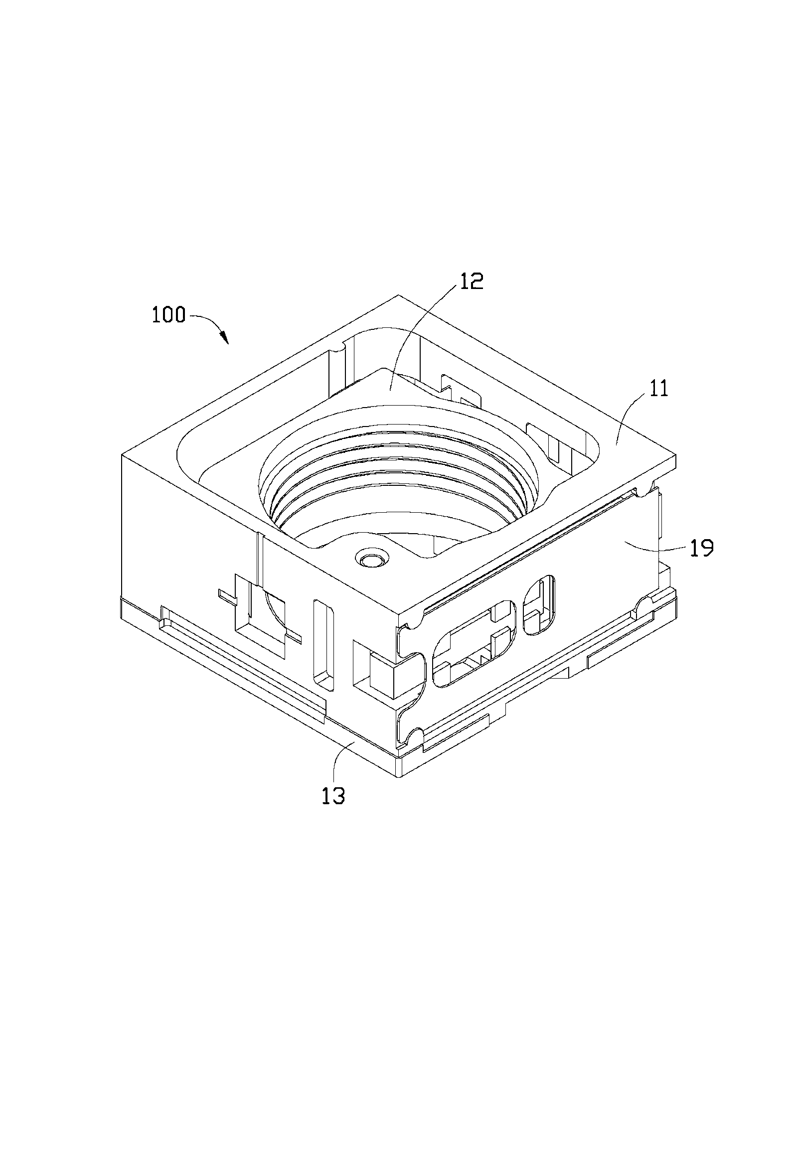
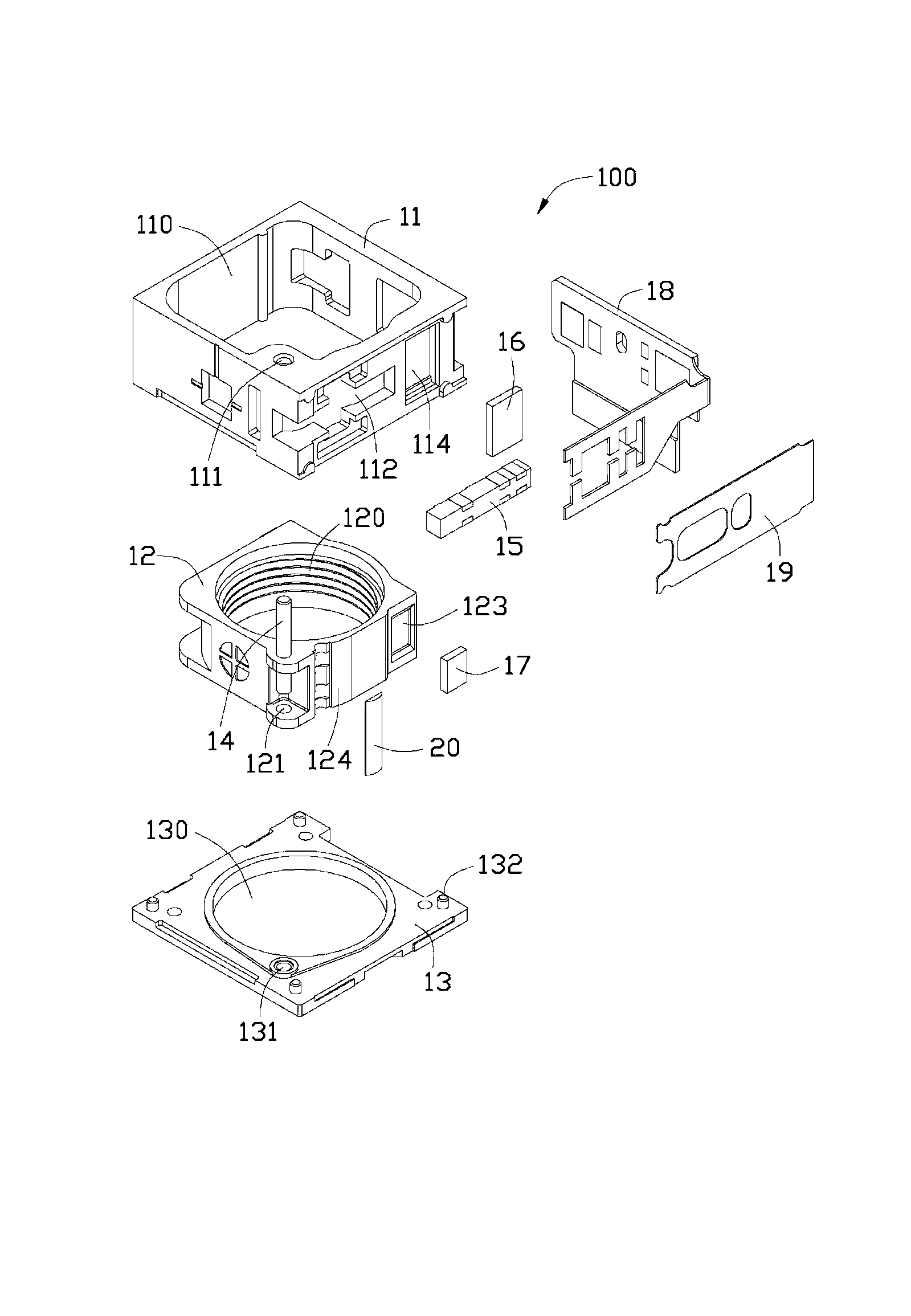
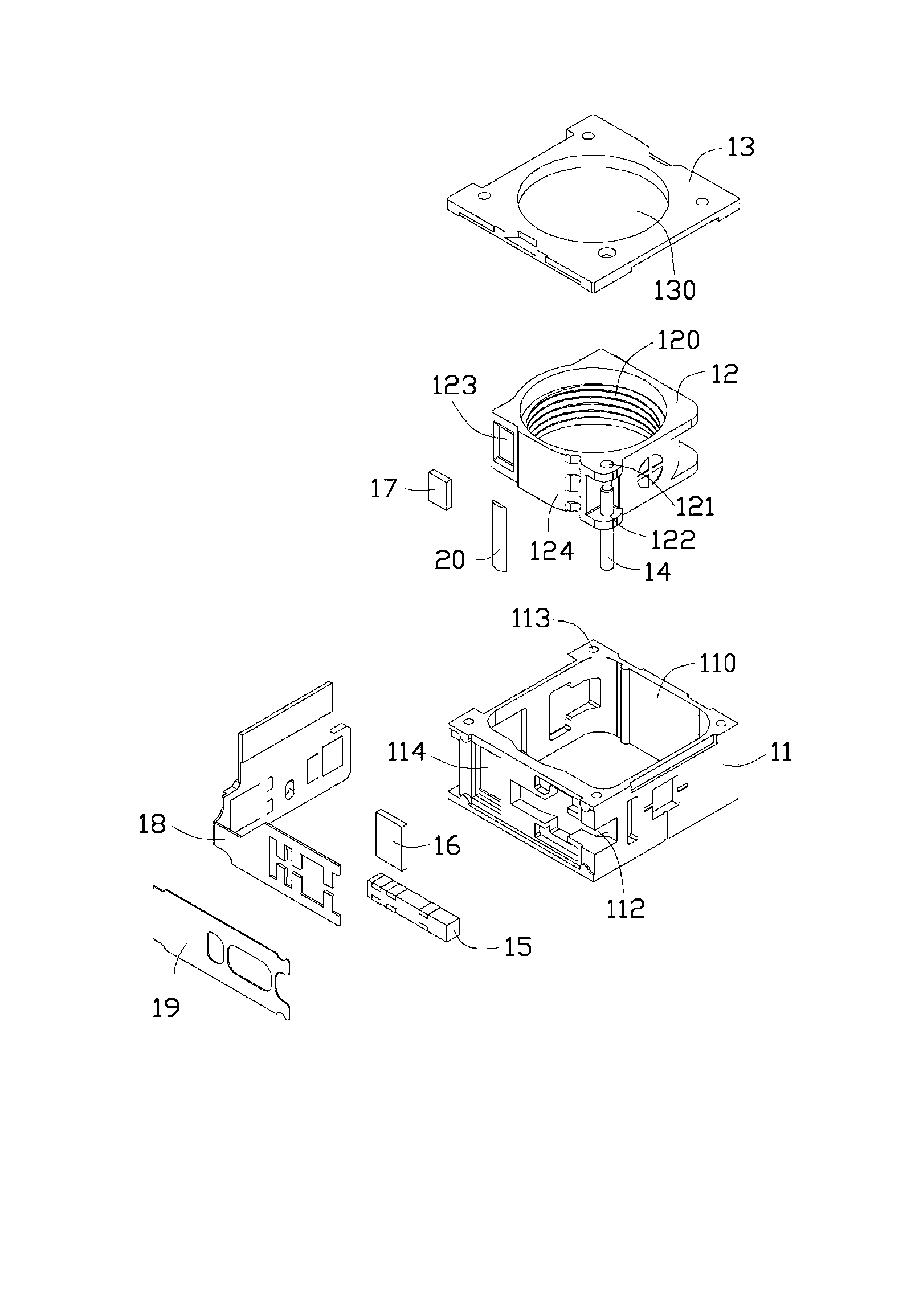
[0016] see figure 1 , figure 2 and image 3 As shown, the driving device 100 provided by the embodiment of the present invention is used to drive the movement of the lens module (not shown) to realize the focusing operation. A piezoelectric unit 15 , a magnetic sheet 16 , a magnet 17 , a circuit board 18 , a holder 19 and a contact rod 20 .

[0017] The circuit board 18 is used to provide electrical energy to the piezoelectric unit 15 to make it work. When the circuit board 18 provides voltage to the piezoelectric unit 15, the piezoelectric unit 15 has mechanical deformation, and the voltage in different directions has mechanical deformation in different directions, and different Different magnitudes of voltage have different magnitudes of mechanical deformation. The circuit board 18 can be a general printed circuit board or a flexible circuit board (FPCB).

[0018] The fixing frame 11 has a square structure with a first receiving space 110 for receiving the movable eleme...


PUM


Abstract

A driving device is used for driving a lens module to move. The driving device comprises a fixing support, a movable piece, a magnetic plate, a magnet, a supporting body, a guiding rod, a contact rod and a piezoelectric unit. The fixing support is provided with an accommodating space and an opening. The movable piece is arranged in the accommodating space and provided with a through hole. The magnetic plate is fixed on the fixing support. The magnetic is fixed on the movable piece, and acting force between the magnet and the magnetic plate can fix the movable piece on a preset position in the fixing support. The supporting body is matched with the fixing support and used for accommodating the movable piece. The guiding rod penetrates through the through hole of the movable piece, and two ends of the guiding rod are fixed on the fixing support and the supporting body respectively. The contact rod is fixed on the movable piece. The piezoelectric unit is fixed in the opening, butts against the contact rod and is used for deforming to generate friction between the piezoelectric unit and the contact rod to drive the movable piece to move in the accommodating space along the guiding rod.

Description

technical field [0001] The invention relates to a driving device, in particular to a driving device using a piezoelectric unit. Background technique [0002] A digital camera or a mobile phone with a shooting function is equipped with at least one lens module, and the function of the lens module is to drive the optical lens or the optical lens group to move along the optical axis to achieve auto-focus and / or zoom functions. [0003] One of the moving methods of the optical lens group is a piezoelectric motor, which has a piezoelectric unit and a contact rod in contact with the piezoelectric unit. , the movable part can be fixed without moving, so as to prevent damage to the lens module), it is realized by using two magnets to attract the contact rod fixed on the movable part, and the magnet is located on the two sides of the optical axis path of the optical lens group At the end, the piezoelectric unit is located between the two magnets, the piezoelectric unit is deformed, ...

Claims


Application Information

Patent Timeline
IPC IPC(8): G02B7/09G03B13/36H02K33/18
Inventor 黄建玮
Owner HONG FU JIN PRECISION IND (SHENZHEN) CO LTD
Why Eureka
Try Eureka